5. Optional: If you must remove the node from the rack to work on it, perform the following procedure
to remove all cables and remove the node from the rack:
a. To make sure that you can replace all cables in the same ports from which they were removed,
label the port position of each fibre-channel and Ethernet cable; then remove all cables from the
back of the node.
b. Remove the node from the rack and place it on a flat, static-protective surface. See “Removing the
SAN Volume Controller from a rack” on page 40.
6.
7. Remove the service controller from the SAN Volume Controller 2145-CF8, as described in “Removing
the SAN Volume Controller 2145-CF8 service controller” on page 75.
8. Remove or replace the USB service-controller cable.
To remove the USB service-controller cable, perform the following procedure:
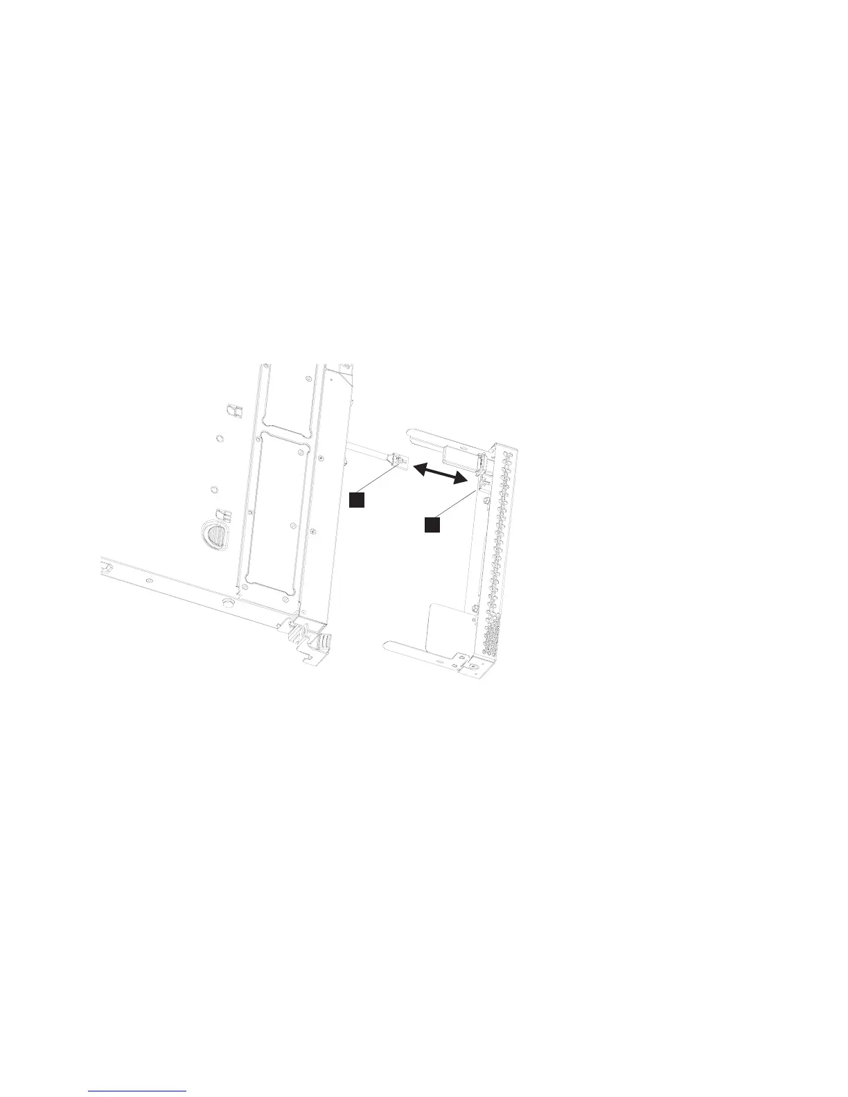
a. Disconnect the USB cable (1 in Figure 79) from the service controller (2).
1 USB cable
2 USB connector
b. Locate the USB connector (1 in Figure 80 on page 80) on the left side of the SAN Volume
Controller 2145-CF8.
1
2
Svccontrollercable_cf8
Figure 79. Removing and replacing the USB cable in the SAN Volume Controller 2145-CF8 service controller
Chapter 2. Removing and replacing parts 79