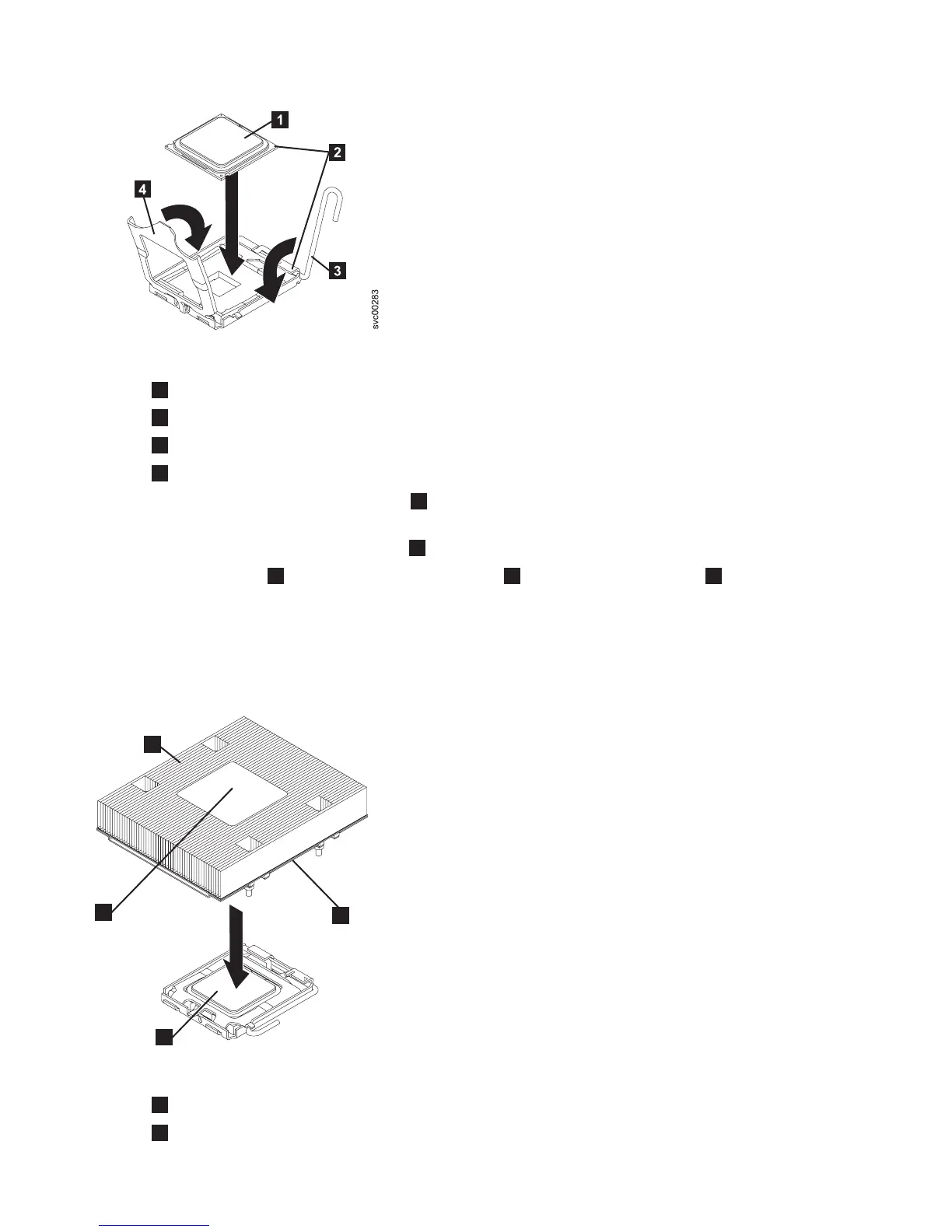
1
Microprocessor
2
Alignment marks
3
Microprocessor release lever
4
Microprocessor bracket frame
5. Place the microprocessor bracket frame
4
down over the microprocessor and the microprocessor
socket to secure the microprocessor position in the socket.
6. Rotate the microprocessor release lever
3
into a closed position.
7. Place the heat sink
1
on top of the microprocessor
3
with the thermal grease
2
side down, as
shown in Figure 260. Tighten the captive screws to secure the heat sink to the system board.
Alternate among the screws on either side of the heat sink until they are snug, and then alternate
again until they are tight, making sure that you do not overtighten any of them.
Attention: If you are working on a Rev 1 node, do not touch the thermal grease on the bottom of
the heat sink after you remove the plastic cover. Touching the thermal grease contaminates it.
1
Heat sink
2
Thermal grease
Figure 259. Aligning the microprocessor with the socket
1
2
3
4
svc00281
Figure 260. Installing the heat sink
236 IBM SAN Volume Controller Hardware Maintenance Guide