v You must remove a number of components before you can remove and replace the system board. You
will reuse all the components that are removed with the new system board. Therefore, take care when
you remove and store these components.
v Each connector on the system board has its use printed next to it on the board.
To remove the system board, perform the following steps:
1. Read the safety precautions in “Safety and environmental notices” on page xiii.
2. Ensure that the node is turned off. If the node is an active member of a cluster, you must take care
not to turn off the only node that services one or more VDisks, because the host applications will
lose access to their data. See MAP 5350 in the IBM System Storage SAN Volume Controller 2145
Troubleshooting Guide.
3. Remove the cable-retention bracket and disconnect the power cable from the node. See “Removing
the cable-retention bracket” on page 29.
4. Remove the node from the rack and place it on a flat, static-protective surface. See “Removing the
SAN Volume Controller from a rack” on page 40.
5.
6. Remove the riser-card and fibre-channel adapter. Place them on a static-protective surface for
reinstallation. You do not need to separate the riser-card and fibre-channel adapter assembly. See
“Removing the fibre-channel adapter assembly” on page 161.
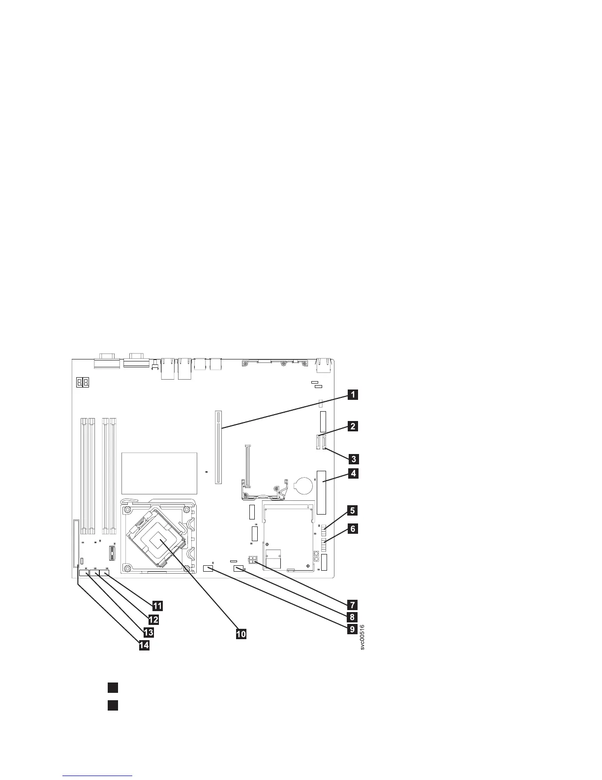
7. Mark the cables to ensure that you know where each one goes. Figure 265 shows the connectors on
the SAN Volume Controller 2145-8A4 system board.
1
PCI express riser card connector
2
SATA 2 connector
Figure 265. Connectors that are used on the SAN Volume Controller 2145-8A4 system board
Chapter 2. Removing and replacing parts 243