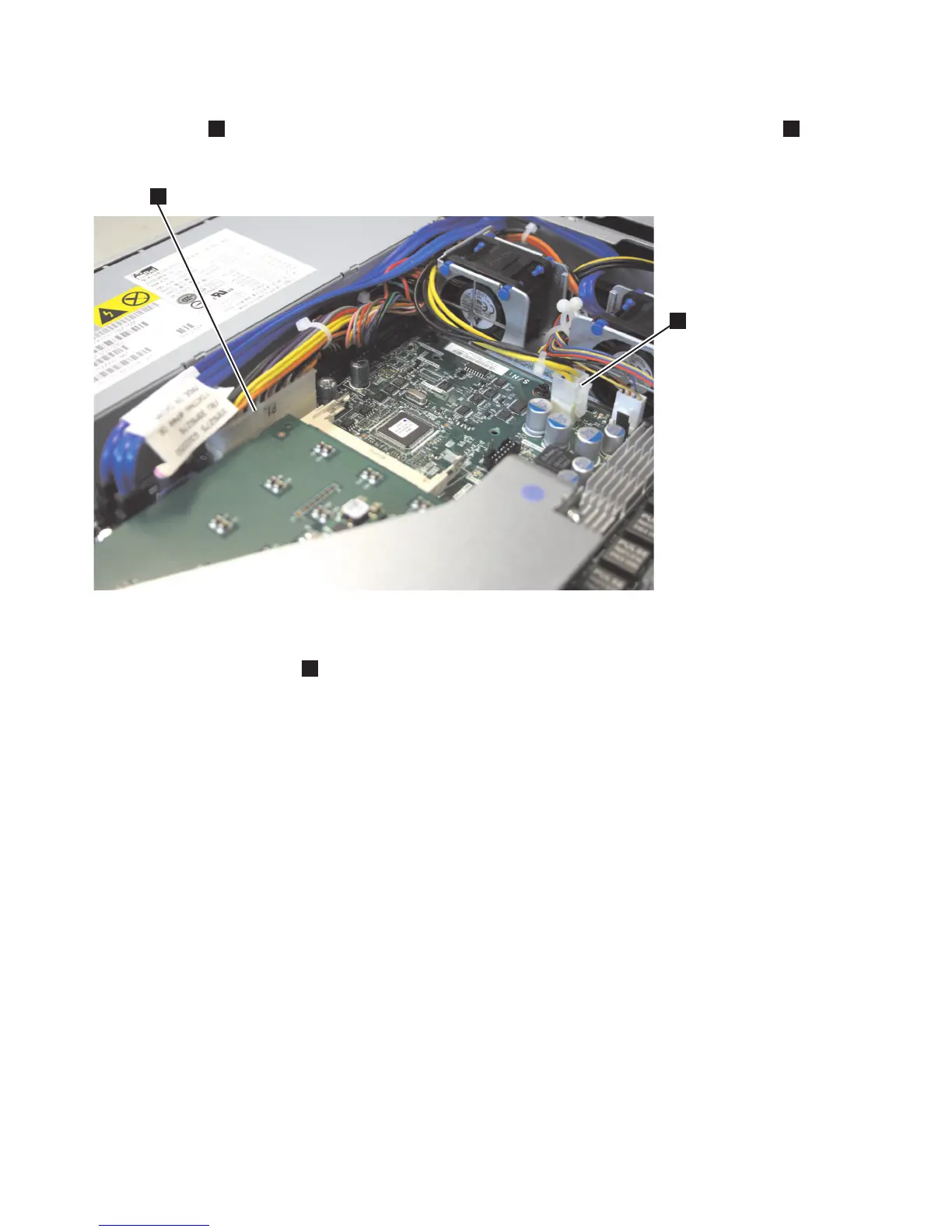
5. There are two cables to connect to the system board, as shown in Figure 160. Connect the cable
labeled P1
1
to the position marked 24 PIN POWER CONN. Connect the cable labeled P6
2
to
the position marked POWER.
6. Route the power-supply cable with the P5 connector to the CD/DVD interface card and secure it
under the retention-clip
1
, as shown in Figure 161 on page 151, on the chassis.
svc00484
1
2
Figure 160. SATA connectors on the SAN Volume Controller 2145-8A4 system board
150 IBM SAN Volume Controller Hardware Maintenance Guide