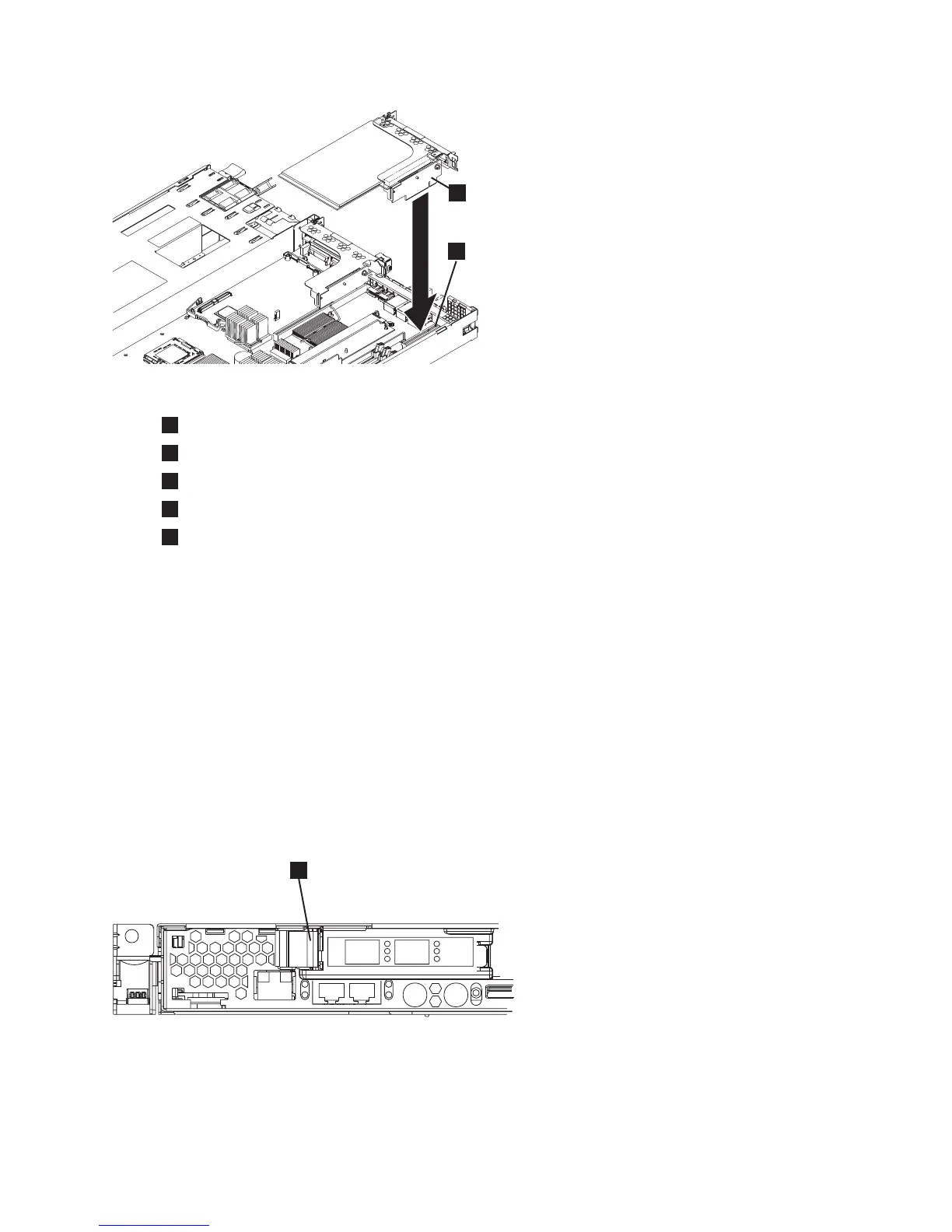
1
Fibre-channel adapter
2
Adapter support bracket
3
Riser-card-adapter connector
4
Riser-card assembly
5
System-board-riser-card connector
2. Replace the top cover. See “Replacing the top cover” on page 72.
3. Place the node in the rack. See “Replacing the SAN Volume Controller in a rack” on page 48.
4. Replace the cables that were removed from the node, and make sure that you replace the
fibre-channel cables in the same ports from which they were removed.
5. Replace the cable-retention bracket. See “Replacing the cable-retention bracket” on page 34.
Replacing the SAN Volume Controller 2145-8F4 or SAN Volume Controller
2145-8F2 adapter assemblies
Perform the following steps to install the fibre-channel card into the riser-card assembly:
Note: The adapter assemblies are electrostatic-discharge sensitive. Take precautions to avoid damage
from static electricity. Wear an anti-static wrist strap and use a static-protected mat or surface. For more
information, see “Handling static-sensitive devices” on page xix.
1. Install the fibre-channel card in slot 1, which is shown in Figure 187.
a. Slide the I/O connector portion of the adapter through the slot 1 opening and align the edge
connector on the low-profile adapter with the connector on the riser card. Press the edge connector
firmly into the riser-card connector. Make sure that the adapter snaps into the riser card securely
and the adapter is lying on top of the low-profile adapter support.
2
svc00253
1
Figure 186. Replacing the riser-card assembly for the SAN Volume Controller 2145-8G4
svc00100
1
Figure 187. SAN Volume Controller 2145-8F2 or SAN Volume Controller 2145-8F4 PCI slot 1 card retainer
Chapter 2. Removing and replacing parts 171