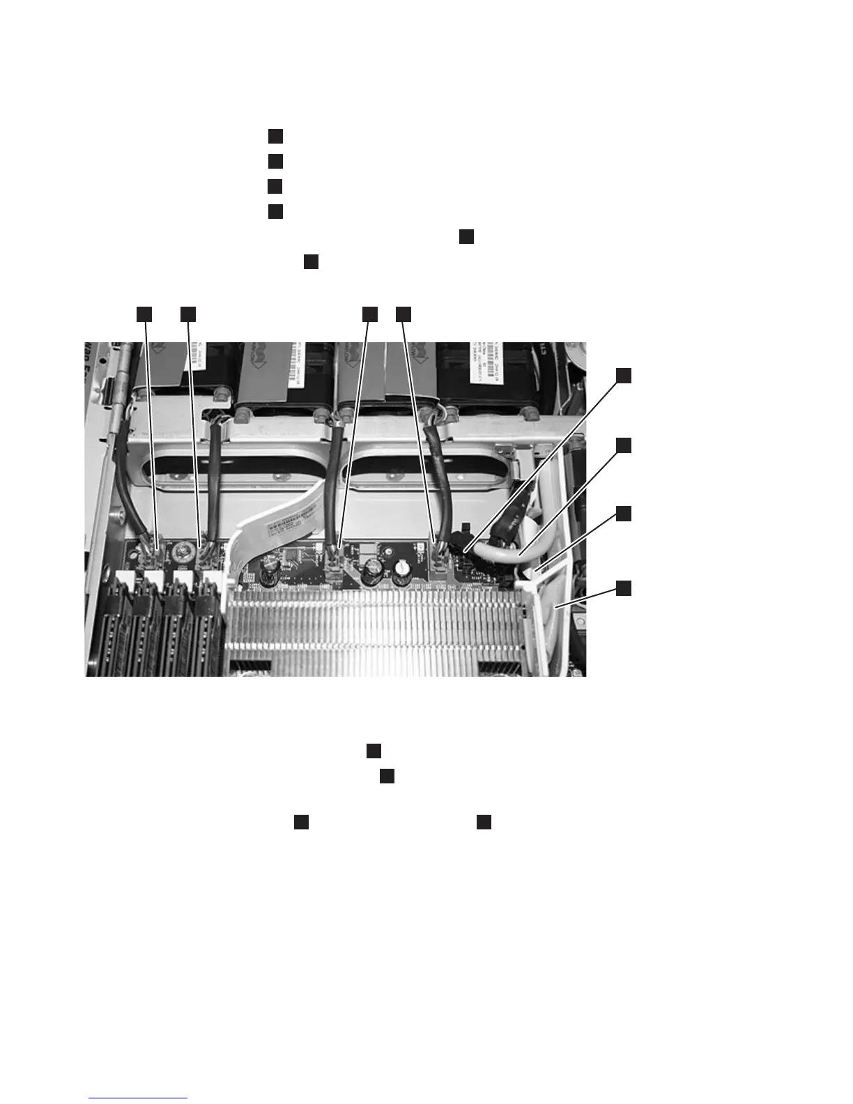
9. Disconnect the connectors from the system board, which are shown in Figure 273. From the right
front side of the system board, remove the following:
a. The fan 3 connector
5
by pressing the release latch in the center and then pulling up.
b. The fan 4 connector
6
by pressing the release latch in the center and then pulling up.
c. The fan 5 connector
7
by pressing the release latch in the center and then pulling up.
d. The fan 6 connector
8
by pressing the release latch in the center and then pulling up.
e. The uninterruptible power supply cable connector
4
.
f. The video cable connector
3
.
10. Remove the remaining cables from the system board:
a. The CD-RW ribbon cable connector
1
by gently pulling the connector upward.
b. The light path ribbon cable connector
2
by gently pulling the connector upward.
All cables should now have been removed from the system board. You do not need to disconnect the
disk power cable connector
1
on the power backplane
2
, which are shown in Figure 274 on page
251.
svc00378
1
3
4
5
6
7
8
2
Figure 273. Connectors on the right front side of the SAN Volume Controller 2145-8G4 system board
250 IBM SAN Volume Controller Hardware Maintenance Guide