3. Press firmly until the back plate is fully seated and the locking tab
1
snaps into place.
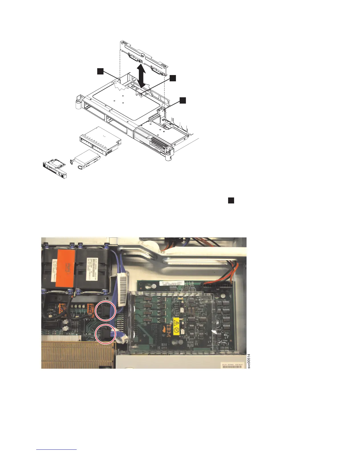
4. Reconnect the power cable to the power supply backplane card. Then reconnect the two blue signal
cables to the system board. The left cable goes to the front system board connector and the right
cable goes to the rear system board connector, as shown in Figure 132.
5. Install the hard disk drive. See “Replacing the disk drive” on page 107.
6.
7. Replace the top cover. See “Replacing the top cover” on page 72.
8. Place the node in the rack. See “Replacing the SAN Volume Controller in a rack” on page 48.
1
svc00306
2
2
Figure 131. The SAN Volume Controller 2145-8G4 SATA disk drive and back plate
Figure 132. The SAN Volume Controller 2145-8G4 disk-drive backplane connectors
Chapter 2. Removing and replacing parts 127