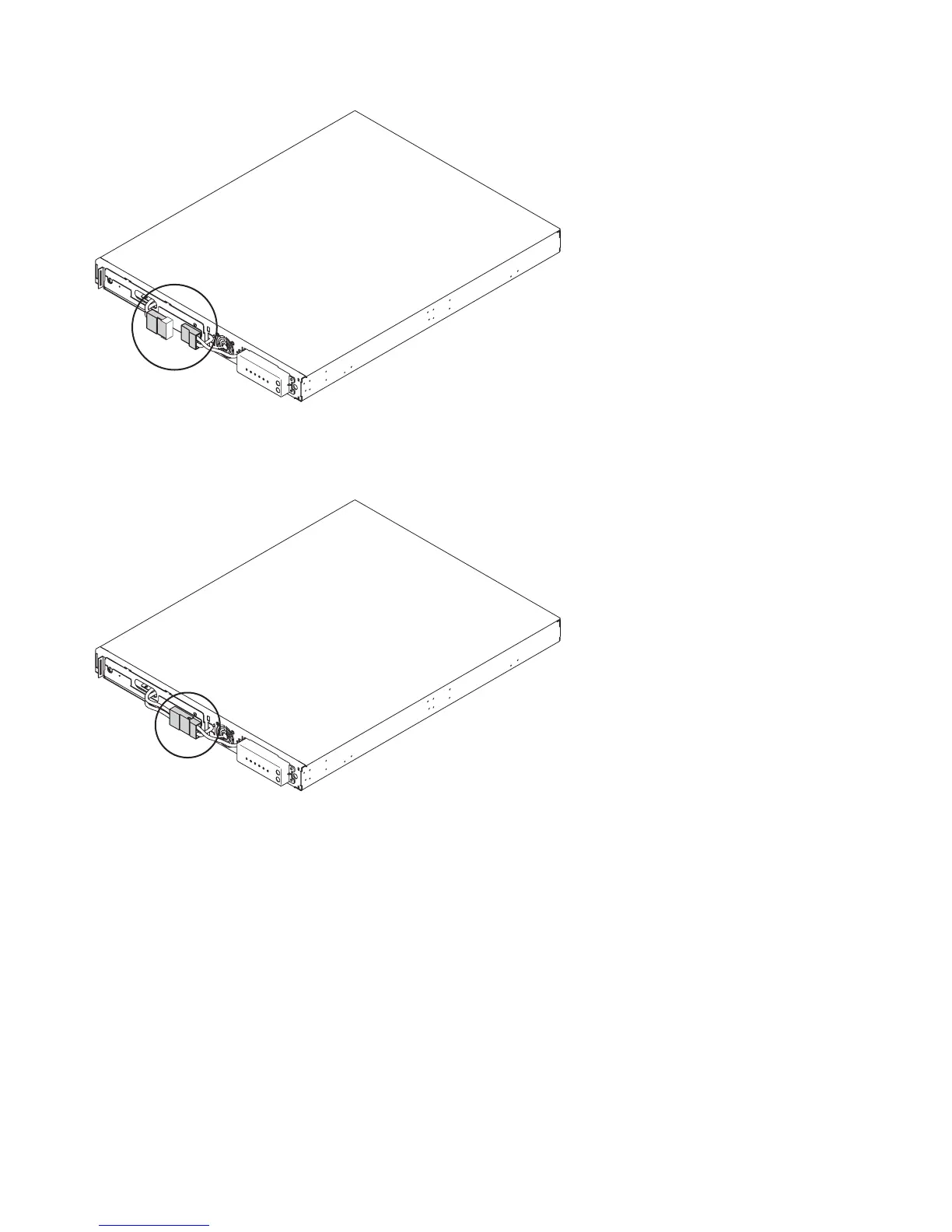
7. Connect the internal battery connector (circled in Figure 308).
Note: A small amount of arcing may occur when connecting the batteries. This is normal and does
not damage the unit or present any safety concerns.
8. Reinstall the front panel.
9. At the back of the 2145 UPS-1U, connect the SAN Volume Controller power cable to load segment 2
receptacle (3 in Figure 310 on page 279). If applicable, install the power cable-retention bracket
(shown in Figure 309 on page 279).
Note: The 2145 UPS-1U is intended to maintain power on a single SAN Volume Controller node
until data can be saved to the local hard disk drive. Only SAN Volume Controller nodes can be
plugged in to the 2145 UPS-1U or else the SAN Volume Controller cluster malfunctions. You must
attach only one SAN Volume Controller to the 2145 UPS-1U, and nothing else.
svc00062
Figure 307. The 2145 UPS-1U internal battery connector with protective tape
svc00061
Figure 308. The 2145 UPS-1U with internal battery connectors in place
278 IBM SAN Volume Controller Hardware Maintenance Guide