2. Remove the SAN Volume Controller 2145-8F4 cable retention bracket.
3. To make sure that you can replace all cables in the same ports from which they were removed, record
the position of all fibre-channel and Ethernet cables; then remove all cables from the back of the node.
4. Remove the node from the rack and place it on a flat, static-protective surface. See “Removing the
SAN Volume Controller from a rack” on page 40.
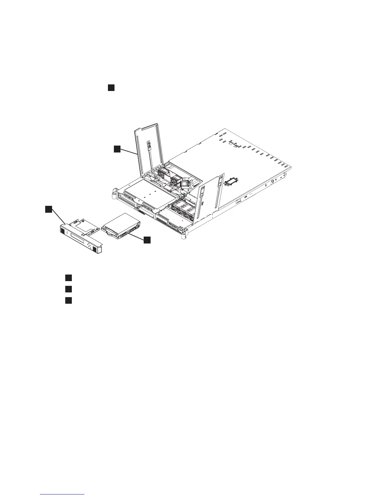
5. Open fan door A (
1
in Figure 102).
6. Remove the service controller. See “Removing the service controller” on page 75.
7. Pull the disk drive out of the bay.
1
Fan door A
2
Service controller
3
SATA disk drive
You can now replace the SAN Volume Controller 2145-8F2 or SAN Volume Controller 2145-8F4 disk
drive.
Removing the SAN Volume Controller 2145-4F2 disk drive
Attention:
v Handle the disk drive with care and keep it away from strong magnetic fields.
v The disk drive is electrostatic-discharge (ESD) sensitive. Take precautions to avoid damage from static
electricity. Wear an anti-static wrist strap and use a static-protected mat or surface. For more
information, see “Handling static-sensitive devices” on page xix.
To remove the disk drive and cables, perform the following steps:
1. Verify that all operations between the node and the host system have been stopped.
2. Turn off the node while ensuring that its data is mirrored and synchronized. See MAP 5350 in the
IBM System Storage SAN Volume Controller 2145 Troubleshooting Guide for more information.
3. Remove the node from the rack and place it on a flat, static-protective surface. See “Removing the
SAN Volume Controller from a rack” on page 40.
4.
svc00129
1
2
3
Figure 102. Removing the SATA disk drive
Chapter 2. Removing and replacing parts 101