3. Remove the cable-retention bracket and disconnect the power cable from the node. See “Removing
the cable-retention bracket” on page 29.
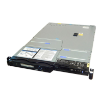
4. Remove the node from the rack and place it on a flat, static-protective surface. See “Removing the
SAN Volume Controller from a rack” on page 40.
5.
6. Remove the SATA back plate far enough to disconnect the two power cables from it. See “Removing
the disk-drive backplane” on page 115.
7. Disconnect the power-supply cables from the 24 PIN POWER connector
1
and the POWER
connector
2
on the system board, as shown in Figure 151.
8. Disconnect the power cable, connector P5, which is shown in Figure 152 on page 144, from the
CD/DVD interface card.
svc00484
1
2
Figure 151. SATA connectors on the SAN Volume Controller 2145-8A4 system board
Chapter 2. Removing and replacing parts 143
 Loading...


