8. Install the redundant ac-power switch in the rack. The four “C” clips for mounting the unit should
already be positioned in the rack mounting bar.
9. Position the redundant ac-power switch in the rack, pushing the cables through to the front of the
rack. Mount in place using the four M6 screws.
10. Connect the redundant ac-power switch power input cables to the site power.
a. Determine a suitable cable route from the redundant ac-power switch to the power distribution
units.
b. Route the main input power cable of the redundant ac-power switch to the specified power
distribution unit, and connect it.
c. Route the backup input power cable of the redundant ac-power switch to the specified power
distribution unit, and connect it.
d. Verify that the redundant ac-power switch power cables are tidy. Ensure that they do not obstruct
other equipment and are tied in place where necessary.
11. Test the redundant ac-power switch before connecting it to the 2145 UPS-1U, using MAP 5340 in the
IBM System Storage SAN Volume Controller 2145 Troubleshooting Guide .
12. Connect the one or two 2145 UPS-1U units that are powered by this redundant ac-power switch. The
power cables should still be plugged into the 2145 UPS-1U units.
a. Connect the other end into the output power sockets on the front of the redundant ac-power
switch.
b. Check the labels on the cables to see which socket they should be connected to.
c. If the uninterruptible power supply units do not power on automatically, power them on by
pressing the power button for five seconds.
13. Power on the one or two SAN Volume Controller nodes connected to this redundant ac-power
switch.
Removing and replacing 2145 UPS-1U parts
The remove and replace procedures for the 2145 UPS-1U field replaceable units are described in the
topics which follow.
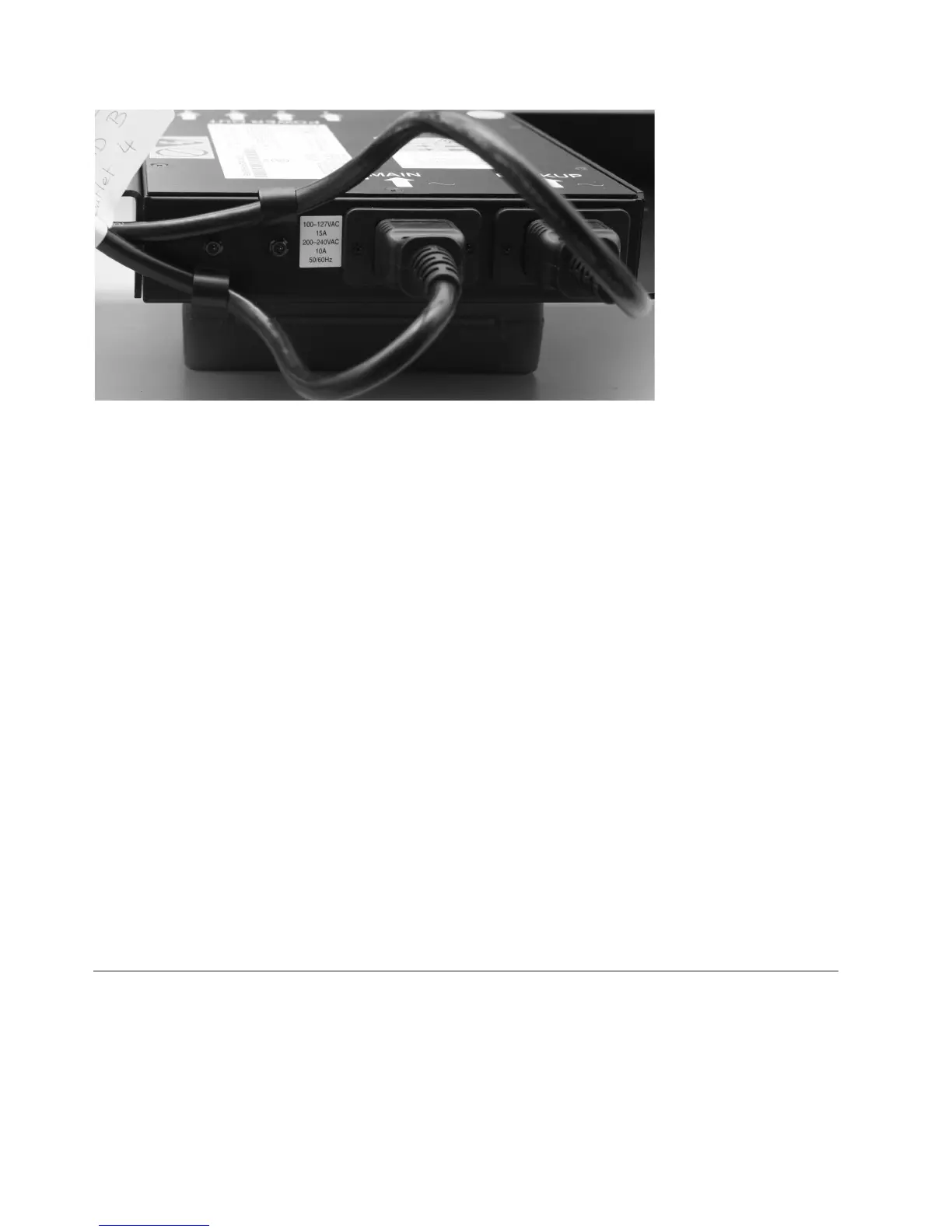
svc00291
Figure 294. Power cable clips
270 IBM SAN Volume Controller Hardware Maintenance Guide