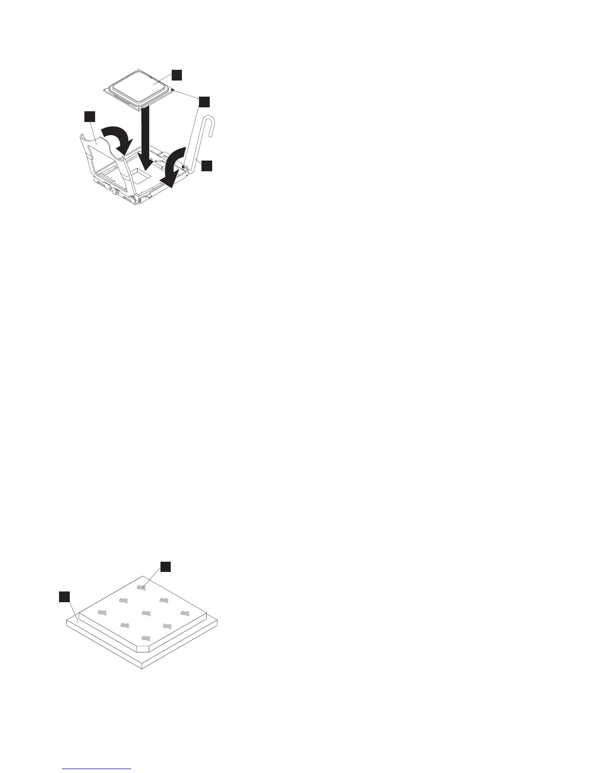
1 Microprocessor
2 Microprocessor-release lever
3 Microprocessor-bracket frame
6. Carefully close the microprocessor-release lever (2) to the closed position to secure the
microprocessor in the socket.
7. Clean the grease from the heat sink and apply new grease on the microprocessor.
When you are installing the heat sink on the same microprocessor that it was removed from, make
sure that the following requirements are met:
v The thermal grease on the heat sink and microprocessor is not contaminated.
v Additional thermal grease is not added to the existing thermal grease on the heat sink and
microprocessor.
To replace damaged or contaminated thermal grease on the microprocessor and heat sink, complete
the following steps:
a. Place the heat sink on a clean work surface.
b. Remove the cleaning pad from its package and unfold it completely.
c. Use the cleaning pad to wipe the thermal grease from the bottom of the heat sink.
Note: Make sure that all of the thermal grease is removed.
d. Use a clean area of the cleaning pad to wipe the thermal grease from the microprocessor; then,
dispose of the cleaning pad after all of the thermal grease is removed.
e. Use the thermal-grease syringe to place 9 uniformly spaced dots of 0.02 mL each on the top of
the microprocessor, as shown in Figure 253. The outermost dots must be within approximately 5
mm of the edge of the microprocessor to ensure uniform distribution of the grease.
1 Microprocessor
1
2
3
4
Figure 252. Closing the SAN Volume Controller 2145-CF8 microprocessor-bracket frame
2
1
Figure 253. Applying thermal grease to the SAN Volume Controller 2145-CF8 microprocessor
230 IBM SAN Volume Controller Hardware Maintenance Guide