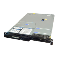
2. Replace the top cover on the node.
3. Replace the node in the rack.
4. Restore all power to the node.
If a node error between 511 and 515 displays on the SAN Volume Controller model 2145-CF8,
2145-8G4, 2145-8F4, 2145-8F2 front panel, complete the following steps:
a. Use the power button to turn off the node.
b. Remove the power cable from the node.
c. Wait 20 seconds and then replace the power cable.
d. Turn on the node.
e. If the error displays again, the memory bank might be disabled.
v For the SAN Volume Controller 2145-CF8, 2145-8A4, 2145-8G4, 2145-8F4, or 2145-8F2 node,
complete the following steps to enable a disabled memory bank:
1) Use the power button to turn off the node.
2) Attach the display and keyboard to the rear panel connectors. No special cables are required.
3) Turn on the node and press F1 until you the setup menu displays.
4) Go to the configuration menu, select Memory, and enable the disabled memory bank.
5) Save the settings, exit the configuration program, and then restart the node.
f. If the error displays again, remove and replace the memory module again to ensure that it is
seated correctly. If that does not resolve the error, the memory module connector might be the
problem. Replace the system board on the SAN Volume Controller models 2145-CF8, 2145-8A4,
2145-8G4, or replace the frame assembly on the SAN Volume Controller 2145-8F4 and SAN Volume
Controller 2145-8F2.
5. Make sure that all cables, adapters, and other components are installed and seated correctly and that
you have not left loose tools or parts inside the node. Make sure that all internal cables are correctly
routed. If you disconnected the fibre-channel and Ethernet cables, make sure that each cable is
reconnected to the same port from which it was removed.
6. Replace the top cover. See “Replacing the top cover” on page 72.
The procedure to replace the top cover also installs the node in the rack and turns on the node.
Removing the disk drive
You might have to remove the disk drive for a service action.
1
2
3
2
1
svc00125
Figure 100. Replacing a memory module
Chapter 2. Removing and replacing parts 99

 Loading...


