5. Replace the top cover. See “Replacing the top cover” on page 72.
6. Place the node in the rack. See “Replacing the SAN Volume Controller in a rack” on page 48.
7. Reconnect the fibre-channel and Ethernet cables. Ensure that you replace the fibre-channel and
Ethernet cables in the same ports from which they were removed.
8. Turn on the node.
Replacing the SAN Volume Controller 2145-8F4 or SAN Volume Controller
2145-8F2 power backplane
The SAN Volume Controller 2145-8F4 or SAN Volume Controller 2145-8F2 power backplane might have
to be replaced.
Take precautions to avoid damage from static electricity. Wear an anti-static wrist strap and use a
static-protected mat or surface. For more information, see “Handling static-sensitive devices” on page xix.
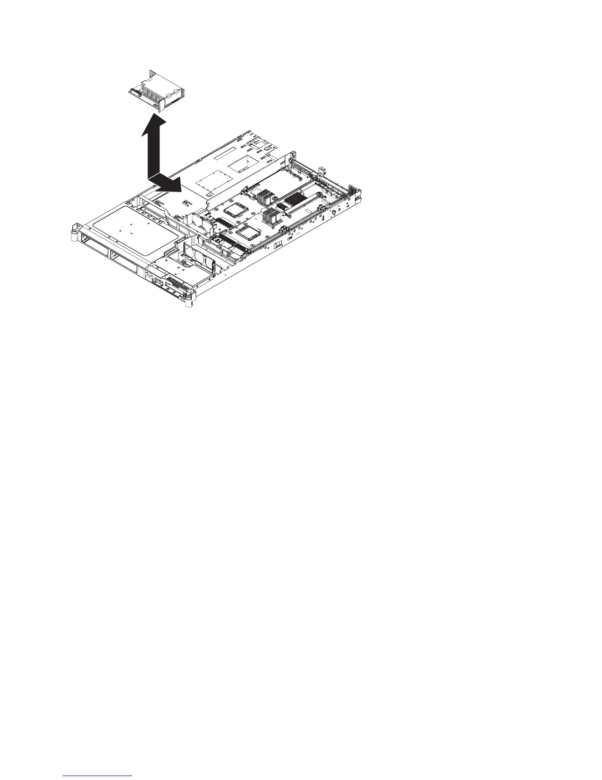
Perform the following steps to replace the power backplane:
1. Lower the power backplane into position on the SAN Volume Controller 2145-8F4 or SAN Volume
Controller 2145-8F2 and slide it to the right to connect it to the system board. See Figure 169 on page
158.
svc00286
Figure 168. SAN Volume Controller 2145-8G4 power backplane
Chapter 2. Removing and replacing parts 157