1 USB connector
2 Disk-controller connector
3 Disk-controller and USB riser-card assembly
Figure 202 shows the USB service-controller cable connected to the disk-controller and USB riser-card
assembly.
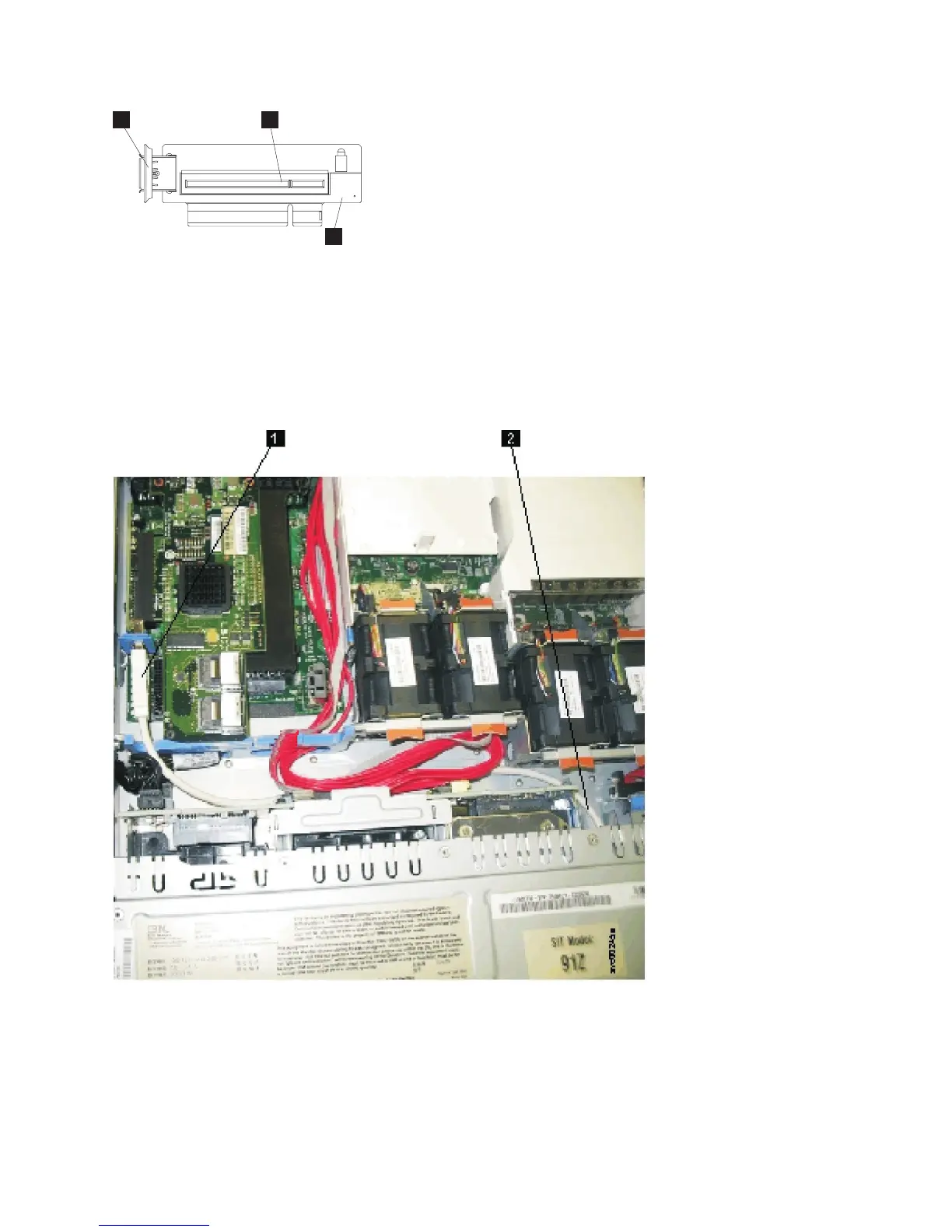
1 USB service-controller cable attached to the USB riser card
2 Service controller cable
9. Connect the SAS boot-drive cable (the cable to drive bays 4 and 5) to the connector on the disk
controller that is closer to the power supplies.
3
1
2
Figure 201. USB riser-card assembly for the SAN Volume Controller 2145-CF8
Figure 202. USB service-controller cable connected to the disk controller and USB riser card in the SAN Volume
Controller 2145-CF8
Chapter 2. Removing and replacing parts 185