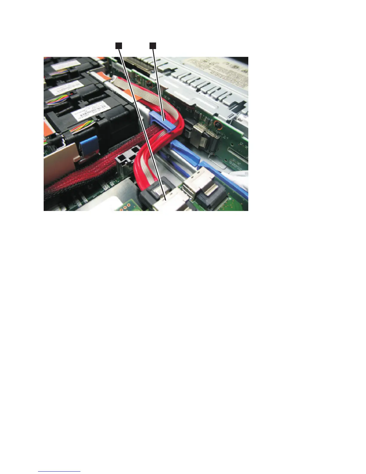
1 Boot-disk SAS cable that is plugged into the disk-controller-and-USB-riser-card assembly
2 Blue bulkhead clip with the high-speed SAS-adapter cable and the boot-disk SAS cable
5. Reinstall the fans, as described in “Replacing the fans” on page 214.
6. Reinstall the cover, as described in “Replacing the top cover” on page 72.
7. Reinstall the disk drives and drive-bay blank electromagnetic compatibility (EMC) filler assemblies,
as described in “Replacing the disk drive” on page 107.
8. Replace the service controller, as described in “Replacing the service controller” on page 85.
9. If you removed the node from the rack, replace the node in the rack, as described in “Replacing the
SAN Volume Controller in a rack” on page 48.
10. If you removed any fibre-channel or Ethernet cables, use the labels you placed on each cable to
replace all fibre-channel and Ethernet cables in the same ports from which they were removed.
11. If you removed the power cords, replace the power cords and the cable-retention brackets, as
described in “Replacing the cable-retention bracket” on page 34.
12. Lift the locking levers (1 in Figure 127 on page 124) on the slide rails and push the server 2 all
the way into the rack until it clicks into place.
21
Figure 126. Boot-disk SAS cable routed through the blue bulkhead clip and connected to the SAS disk controller in the
SAN Volume Controller 2145-CF8
Chapter 2. Removing and replacing parts 123