Attention: To avoid damage to the disk-drive connectors, make sure that the node cover is in place
and fully closed whenever you remove or replace a disk drive.
3. If the service controller is in place, press the release button on the side of the service controller
assembly to release it from the node, but do not disconnect the USB service controller cable. Slide the
service controller from the node and support it somewhere, if possible, or gently suspend the service
controller from the service controller cable.
4. If the drive bay contains a drive-bay blank electromagnetic compatibility (EMC) filler assembly,
remove the filler from the drive bay.
The electromagnetic interference (EMI) integrity and cooling of the node are protected by having all
bays and PCI slots covered or occupied. When you install a drive, save the drive bay blank EMC
filler assembly from the drive bay to cover any later removal of the device.
5. Touch the static-protective package that contains a new drive to any unpainted metal surface on the
node; then, remove the drive from the package and place it on a static-protective surface.
6. Install the drive in the drive bay:
a. Make sure that the tray handle is in the open (unlocked) position.
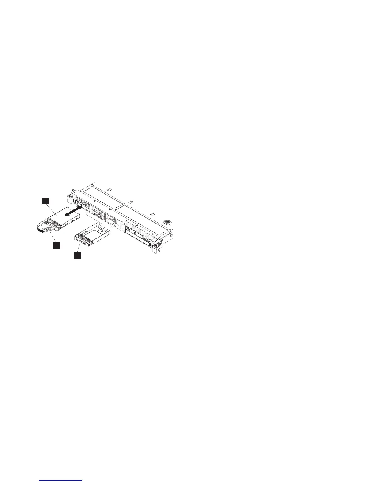
b. Align the drive assembly with the guide rails in the bay, as shown in Figure 115.
1 Solid-state drive (SSD)
2 Drive handle
3 Drive-bay blank electromagnetic compatibility (EMC) filler assembly
c. Gently push the drive assembly into the bay until the drive stops.
d. Rotate the tray handle to the closed (locked) position.
The system error LED and the DASD diagnostics panel LED turn on when a solid-state drive (SSD)
is removed from a drive bay. The system error LED and the DASD diagnostics panel LED turn off
when the SSD is replaced in the drive bay. If you do not replace the SSD in the same drive bay, the
system error LED and the DASD diagnostics panel LED remain lit. To clear the system error LED
and the DASD diagnostics panel LED, turn off the node using the instructions given in MAP 5350 in
the IBM System Storage SAN Volume Controller 2145 Troubleshooting Guide and remove both power
cables.
7. If you are installing additional hot-swap solid-state drives (SSDs), do so now.
8.
9. If you removed the node from the rack, replace the node in the rack, as described in “Replacing the
SAN Volume Controller in a rack” on page 48.
10. Make sure that all cables, adapters, and other components are installed and seated correctly and that
you have not left loose tools or parts inside the node. Make sure that all internal cables are correctly
routed. If you disconnected the fibre-channel and Ethernet cables, make sure that each cable is
reconnected to the same port from which it was removed.
1
2
3
Figure 115. SAN Volume Controller 2145-CF8 drive and drive-bay filler
114 IBM SAN Volume Controller Hardware Maintenance Guide