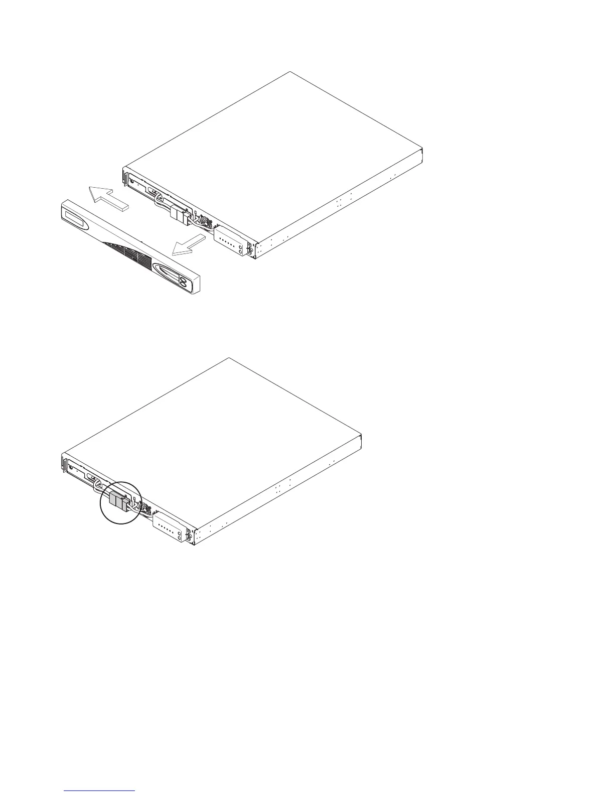
6. Disconnect the internal battery connector, which is circled in Figure 301.
7. After pulling the two connectors apart, cover the exposed battery connector (shown in Figure 302 on
page 275) with adhesive tape.
svc00009
Figure 300. Removing the 2145 UPS-1U front panel
svc00061
Figure 301. The 2145 UPS-1U internal-battery connector
274 IBM SAN Volume Controller Hardware Maintenance Guide