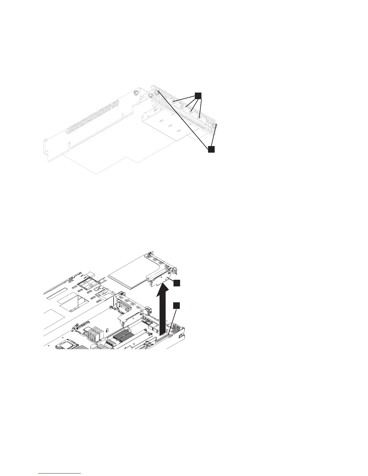
1 Fibre-channel ports1-4
2 Back-rail retaining screws
10. After removing the back-rail retaining screws for the adapter assembly, grasp the riser-card assembly
at either end and pull up out of the slot 1 riser-card connector, as shown in Figure 173. Once the
riser card clears the connector, gently twist the card assembly to separate the assembly from the
node.
When looking from the back, the slot 1 connector is the connector on the left. The high-speed SAS
riser-card assembly, if present, attaches to the slot 2 connector on the left side of the system board,
when looking from the back. If there is no high-speed SAS adapter riser-card assembly, a riser-card
adapter is present in slot 2.
11. Place the riser-card assembly on a flat, static-protective surface.
12. If you are instructed to return the fibre-channel adapter assembly, follow all packaging instructions,
and use any packaging materials for shipping that are supplied to you.
1
2
1
Figure 172. The SAN Volume Controller 2145-CF8 fibre-channel adapter
2
svc00253a
1
Figure 173. Removing the fibre-channel riser-card assembly for the SAN Volume Controller 2145-CF8
Chapter 2. Removing and replacing parts 163