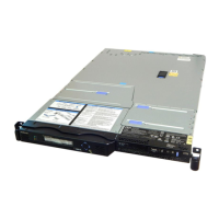
Replacing the SAN Volume Controller 2145-8F4 or SAN Volume Controller
2145-8F2 fans
Take precautions to avoid damage from static electricity. Wear an anti-static wrist strap and use a
static-protected mat or surface. For more information, see “Handling static-sensitive devices” on page xix.
The replacement procedures in this topic assume that the following are true:
v The failed fan is removed
v The node power is turned off
v The node is removed from the rack
Perform the following steps to replace the SAN Volume Controller 2145-8F4 or SAN Volume Controller
2145-8F2 fans:
1. Orient the new fan in the same position as the fan you removed. Make sure that the airflow indicator,
on top of the fan, is pointing to the rear of the server.
2. Push the fan assembly down into the server until the blue grommets are correctly seated.
3. Connect the cable of the replacement fan into the connector.
4. Close the fan door.
5. Replace the top cover. See “Replacing the top cover” on page 72.
6. Place the node in the rack. See “Replacing the SAN Volume Controller in a rack” on page 48.
7. Reconnect the cables and power cords that were removed.
8. Turn on the node.
Removing the SAN Volume Controller 2145-8F2 or SAN Volume
Controller 2145-8F4 fan holder and fan backplanes
The fan holder with fan backplanes field-replaceable unit (FRU) is supplied as a kit of parts. Replace only
the failed assembly and discard any unused part.
Perform the following steps to remove the fan holder with fan backplane:
1. Turn off the node while ensuring that its data is mirrored and synchronized. See MAP 5350 in the
IBM System Storage SAN Volume Controller 2145 Troubleshooting Guide for more information.
2. To make sure that you can replace all cables in the same ports from which they were removed, record
the position of all fibre-channel and Ethernet cables; then remove all cables from the back of the node.
3. Remove the node from the rack and place it on a flat, static-protective surface. See “Removing the
SAN Volume Controller from a rack” on page 40.
4.
5. Unplug the fans from the fan backplane.
6. Remove the screws and set them in a safe place.
7. Disconnect the fan cable.
8. Pull the fan bracket out of the node.
Replacing the SAN Volume Controller 2145-8F2 or SAN Volume
Controller 2145-8F4 fan holder and fan backplanes
The fan holder with fan backplanes field-replaceable unit (FRU) is supplied as a kit of parts. Replace only
the failed assembly and discard any unused part.
Perform the following steps to replace the fan holder with fan backplane:
1. Place the fan bracket into the node.
2. Connect the fan cable.
3. Replace the screws that you had set aside.
220 IBM SAN Volume Controller Hardware Maintenance Guide

 Loading...


