3
Microprocessor
4
Heat sink installation label
8. Replace the top cover. See “Replacing the top cover” on page 72.
9. Place the node in the rack. See “Replacing the SAN Volume Controller in a rack” on page 48.
10. Reconnect the power cable and any other cables that were removed.
11. Turn on the node.
Replacing the SAN Volume Controller 2145-8F4 or SAN Volume Controller
2145-8F2 microprocessor
The SAN Volume Controller 2145-8F4 or SAN Volume Controller 2145-8F2 must always be fitted with
both microprocessors in order to function correctly.
The documented steps to replace the SAN Volume Controller 2145-8F4 or SAN Volume Controller
2145-8F2 microprocessor assume that you:
v Removed all power from the node
v Removed the node from the rack
v Removed the top cover of the node
v Removed the microprocessor that is being replaced
Perform the following steps to replace the SAN Volume Controller 2145-8F4 or SAN Volume Controller
2145-8F2 microprocessor:
1. Touch the static-protective package that contains the new microprocessor to any unpainted metal
surface on the node.
2. Remove the microprocessor from the package.
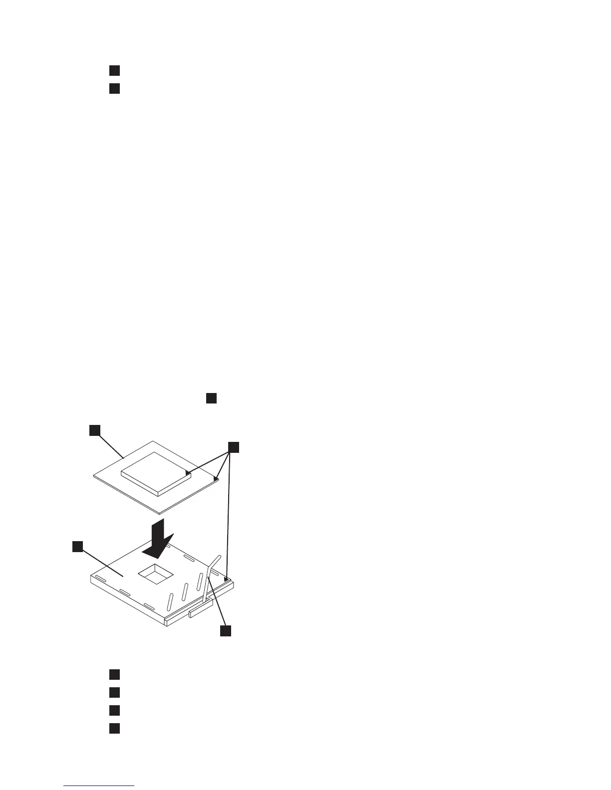
3. Rotate the locking lever
3
from the closed position to the open position, as shown in Figure 261.
1
Microprocessor
2
Corner marks
3
Locking lever
4
Microprocessor socket
1
2
3
4
svc00127
Figure 261. Microprocessor locking lever in open position
Chapter 2. Removing and replacing parts 237