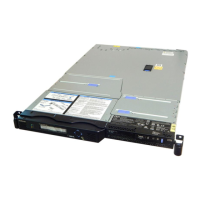
2. Slide the operator-information panel into its cage, as shown in Figure 220, until it locks in place with
a click (in the In position); gently pull the cable through at the back as you do this.
1
Release button
2
Operator-information panel
3. Carefully thread the light path assembly ribbon cable
4
back under its retaining brackets and
replace the tape securing it in place.
4. Thread the light path assembly ribbon cable
4
back to the system board. Reconnect the cable to
the system board socket
11
. In Figure 221, the front of the node is shown at the bottom of the
illustration. The connectors on the cable plug go towards the center of the node and the blue side is
towards the outside of the node.
1
Video cable
1
2
svc00258
Figure 220. SAN Volume Controller 2145-8G4 operator-information panel
Figure 221. SAN Volume Controller 2145-8G4 video, USB, and the CD/DVD cables
200 IBM SAN Volume Controller Hardware Maintenance Guide

 Loading...


