EasyManuals Logo

IBM SAN Volume Controller User Manual

IBM SAN Volume Controller
334 pages
To Next Page IconTo Next Page
To Previous Page IconTo Previous Page
Page #287 background image
3. Replace the four stand-off screws from beside the I/O ports at the rear of the server. Figure 285
shows the location of the stand-off screws.
4. Replace the power backplane by pushing it right to connect it to the system board and pushing the
power supply back in to connect to it. See “Replacing the power backplane” on page 156.
5. Install one of the microprocessors while carefully checking the orientation and remembering to close
the release lever, which is shown in Figure 286 on page 262.
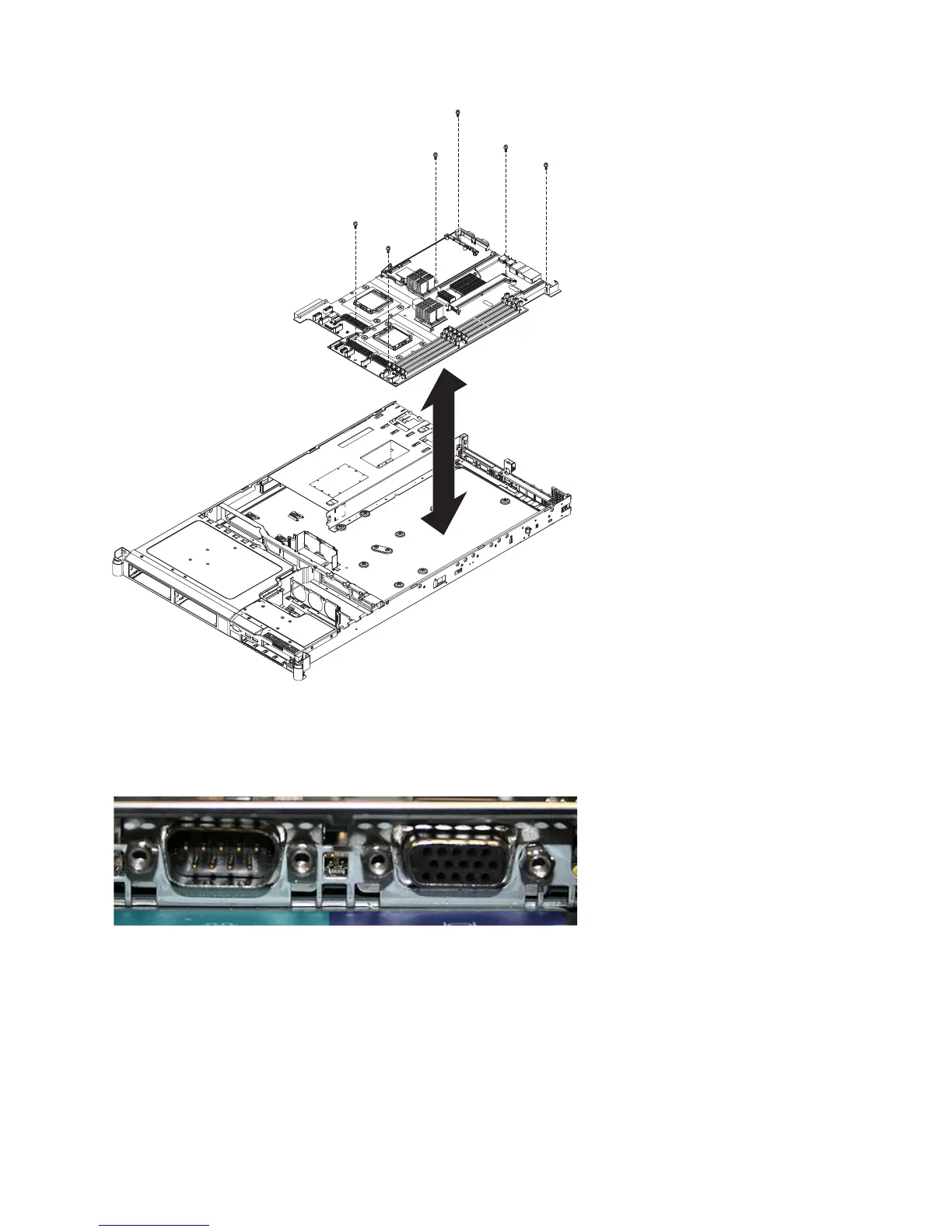
Figure 284. The placement of the screws that secure the SAN Volume Controller 2145-8G4 system board
svc00411
Figure 285. Serial and video ports on the SAN Volume Controller 2145-8G4
Chapter 2. Removing and replacing parts 261

Table of Contents

Questions and Answers:

Question and Answer IconNeed help?

Do you have a question about the IBM SAN Volume Controller and is the answer not in the manual?

IBM SAN Volume Controller Specifications

General IconGeneral
Product NameIBM SAN Volume Controller
CategoryStorage
Storage VirtualizationYes
RAID SupportYes
Compression SupportYes
Encryption SupportYes
Host InterfaceFibre Channel, iSCSI, FCoE, SAS
RAID LevelsRAID 0, 1, 5, 6, 10
Maximum Cache Per System2TB
Supported Drive TypesSSD
High AvailabilityYes

Related product manuals