7. If you removed any fibre-channel or Ethernet cables, use the labels you placed on each cable to
replace all fibre-channel and Ethernet cables in the same ports from which they were removed.
8. If you removed the power cords, replace the power cords and the cable-retention brackets, as
described in “Replacing the cable-retention bracket” on page 34.
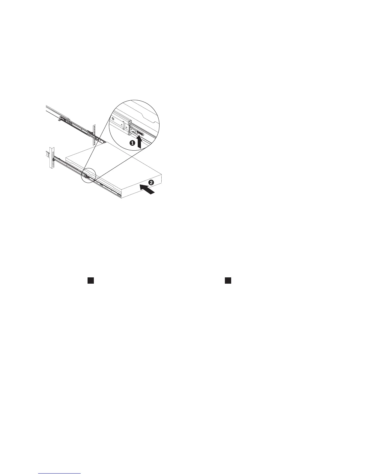
9. Lift the locking levers (1 in Figure 230) on the slide rails and push the server 2 all the way into
the rack until it clicks into place.
10. Turn on the node.
Replacing the SAN Volume Controller 2145-8A4 operator-information panel cable
Use these instructions when you are prompted to replace the operator-information panel cable for the
SAN Volume Controller 2145-8A4.
Perform the following steps to replace the operator-information panel cable:
1. Connect the two connectors at one end of the operator-information panel cable assembly to the Front
USB connector
1
and the Operator-information panel connector
2
on the system board. The
connectors are keyed and it is important to insert the correct connector on the cable assembly onto the
correct connector on the system board.
svc_bb1ka055
Figure 230. Raising the SAN Volume Controller 2145-CF8 locking levers of the slide rails of the rack
208 IBM SAN Volume Controller Hardware Maintenance Guide