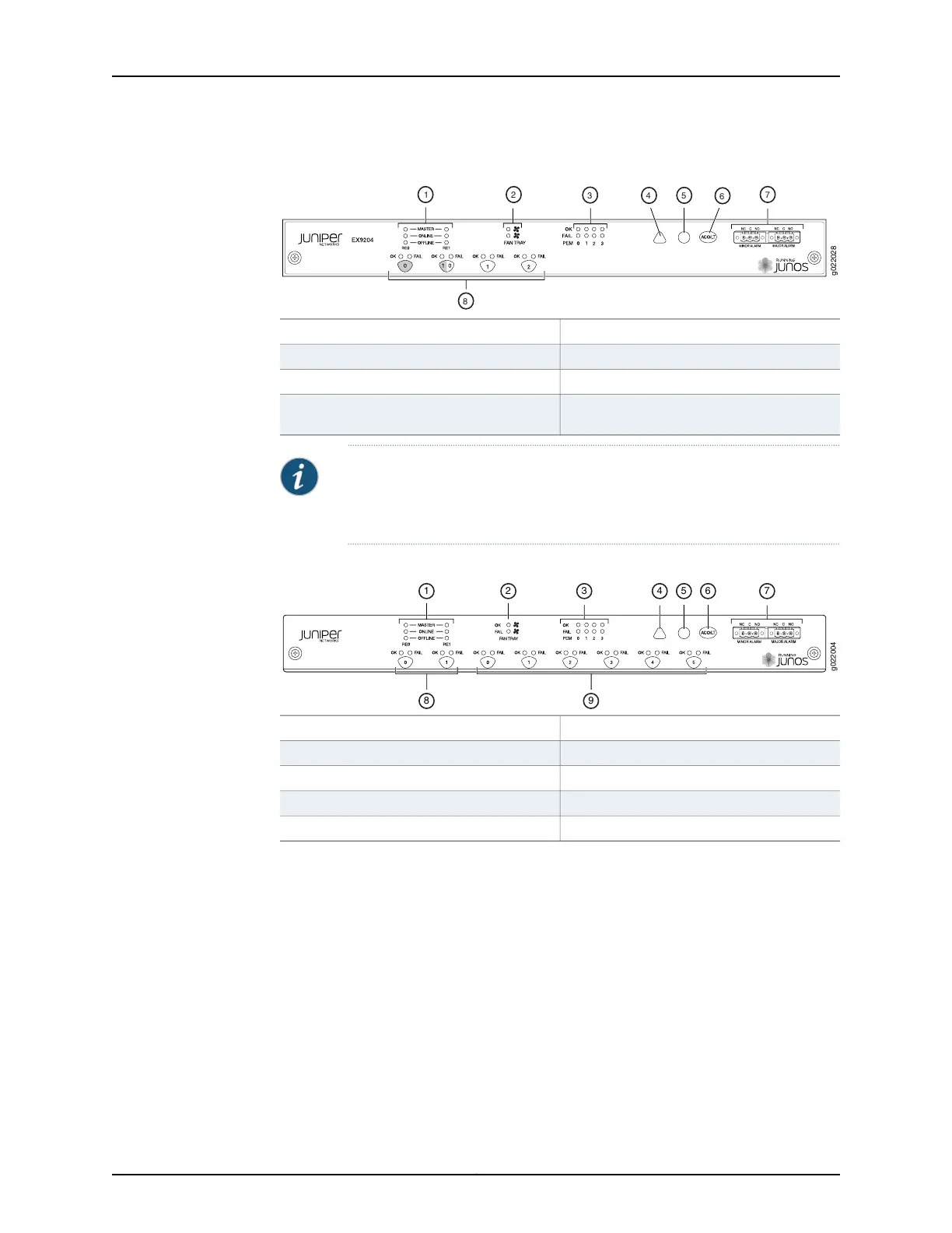
Figure 7: Craft Interface in an EX9204 Switch
5—1— Major alarm LEDHost subsystem LEDs
6—2— Alarm cutoff/lamp test buttonFan LEDs
7—3— Alarm relay contactsPower supply LEDs
8—4— LEDs and control buttons for Switch Fabric
and Line cards
Minor alarm LED
NOTE: You can install a line card or an SF module in the multifunctional slot
labeled 1|0 in EX9204 switches. The corresponding LED displays information
depending on the hardware installed in that slot.
Figure 8: Craft Interface in an EX9208 Switch
6—1— Alarm cutoff/lamp test buttonHost subsystem LEDs
7—2— Alarm relay contactsFan LEDs
8—3— Switch Fabric LEDs and control buttonsPower supply LEDs
9—4— Line card LEDs and control buttonsMinor alarm LED
5—Major alarm LED
Copyright © 2017, Juniper Networks, Inc.20
EX9208 Switch Hardware Guide