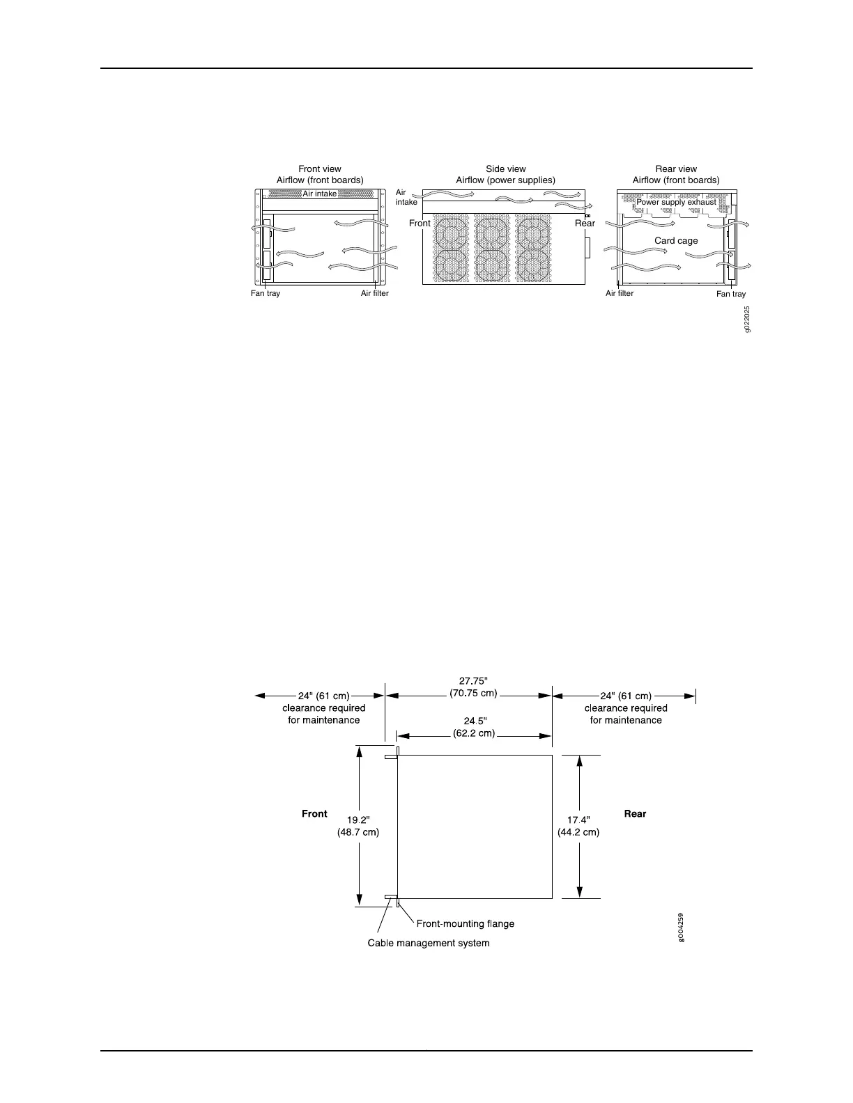
Figure 37: Airflow Through the EX9208 Switch Chassis
Fan tray
Card cage
g022025
Front view
Airflow (front boards)
Side view
Airflow (power supplies)
Front
Air filter Air filter
Air
intake
Air intake
Power supply exhaust
Fan tray
Rear
Card cage
Rear view
Airflow (front boards)
•
If you are mounting the switch on a rack or cabinet along with other equipment, ensure
that the exhaust from other equipment does not blow into the intake vents of the
chassis.
Airflow must always be from front to back with respect to the rack. If the device has
side to rear airflow, then provisions must be made to ensure that fresh air from the
front of the rack is supplied to the inlets, and exhaust exits the rear of the rack. The
device must not interfere with the cooling of other systems in the rack. Fillers must be
used as appropriate in the rack to ensure there is no recirculation of heated exhaust
air back to the front of the rack. Care must also be taken around cables to ensure that
no leakage of air in situations where recirculation may result.
•
For service personnel to remove and install hardware components, there must be
adequate space at the front and back of the switch. At least 24 in. (61 cm) is required
both in front of and behind the switch. NEBS GR-63 recommends that you allow at
least 30 in. (72.6 cm) in front of the rack and 24 in. (61.0 cm) behind the rack. See
Figure 38 on page 89.
Figure 38: Clearance Requirements for Airflow and Hardware Maintenance
for an EX9208 Switch Chassis
89Copyright © 2017, Juniper Networks, Inc.
Chapter 6: Preparation Overview