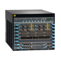
Powering On an AC-Powered EX9200 Switch
Before you power on the switch, ensure that:
•
You have installed all required switch components.
•
You have installed the required number of power supplies to support redundant
operation for the switch configuration.
•
You understand how to protect the switch from electrostatic discharge (ESD) damage
. See “Prevention of Electrostatic Discharge Damage” on page 351.
Ensure that you have the following parts and tools available:
•
An ESD grounding strap.
•
An external management device such as a PC.
•
A cable to connect the external management device to the CONSOLE port or the
Ethernet management <...> port on the master Routing Engine module (RE module).
For connecting a management device to the console port, see “Connecting an EX9200
Switch to a Management Console or an Auxiliary Device” on page 192. For connecting
a management device to the Ethernet management port, see “Connecting an EX9200
Switch to a Network for Out-of-Band Management” on page 191.
To power on the switch:
1. Attach the ESD grounding strap to your bare wrist, and connect the strap to the ESD
point on the chassis.
2. Connect the external management device to the Ethernet management (<...>) port
on the master RE module.
3. Turn on the power to the external management device.
4. Ensure that the power supplies are fully inserted in the chassis and that each of their
handles is flush against the faceplate.
5. Ensure that the source power cord is inserted securely into the appliance inlet for each
AC power supply.
6. Switch on the dedicated customer site circuit breakers for the power supplies. Follow
the ESD and safety instructions for your site.
7. Flip the AC input switch on the power supply to the On (|) position. Observe the power
supply faceplate LEDs. If the power supply is installed correctly and functioning
normally, the AC OK and DC OK LEDs glow steady green. The PS FAIL LED does not
glow.
8. Repeat Step 7 for the remaining power supplies installed in the switch.
If any of the status LEDs indicates that the power supply is not functioning normally,
repeat the installation and cabling procedures. See Connecting AC Power to an EX9204
Copyright © 2017, Juniper Networks, Inc.182
EX9208 Switch Hardware Guide

 Loading...