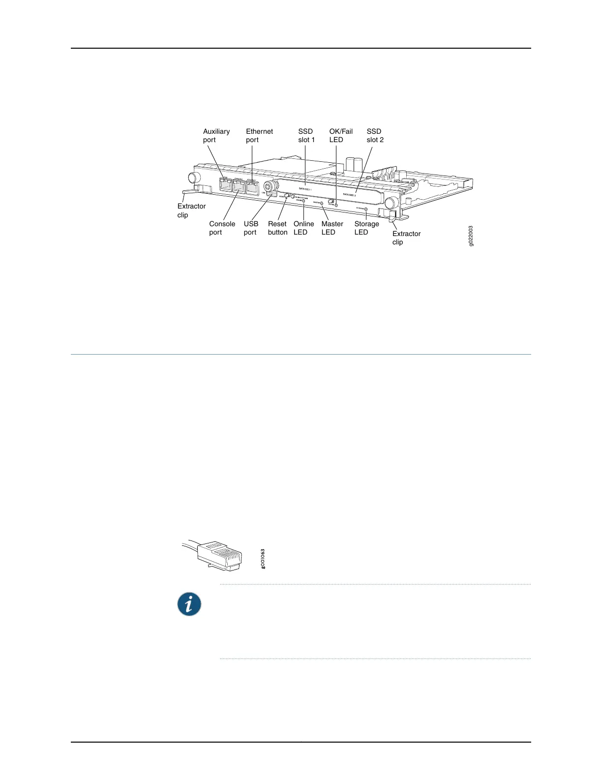
Figure 55: Ethernet Management Port on the RE Module in EX9200
Switches
g022003
USB
port
Reset
button
Online
LED
Master
LED
OK/Fail
LED
Storage
LED
Extractor
clip
Extractor
clip
Console
port
Auxiliary
port
Ethernet
port
SSD
slot 2
SSD
slot 1
Related
Documentation
Connecting an EX9200 Switch to a Management Console or an Auxiliary Device on
page 192
•
• Ethernet Port Connector Pinout Information for an EX9200 Switch
• Cables Connecting the EX9200 Switch to Management Devices
Connecting an EX9200 Switch to a Management Console or an Auxiliary Device
To use a system console to configure and manage the Routing Engine, connect it to the
appropriate Console (CONSOLE) port on the Routing Engine module (RE module). To
use a laptop, modem, or other auxiliary device, connect it to the auxiliary (AUX) port on
the RE. Both ports accept a cable with an RJ-45 connector. One serial cable with an RJ-45
connector and a DB-9 connector is provided with the switch. To connect a device to the
CONSOLE port and another device to the AUX port, you must supply an additional cable.
Ensure that you have an Ethernet cable with an RJ-45 connector available. An RJ-45
cable and an RJ-45 to DB-9 serial port adapter are supplied with the device.
Figure 56 on page 192 shows the RJ-45 connector of the Ethernet cable supplied with the
switch.
Figure 56: Ethernet Cable Connector
NOTE: If your laptop or PC does not have a DB-9 male connector pin and you
want to connect your laptop or PC directly to the device, use a combination
of the RJ-45 to DB-9 female adapter supplied with the device and a USB to
DB-9 male adapter. You must provide the USB to DB-9 male adapter.
To connect the device to a management console or auxiliary device:
1. Turn off the power to the console or auxiliary device.
Copyright © 2017, Juniper Networks, Inc.192
EX9208 Switch Hardware Guide