Two threaded inserts (PEM nuts) are provided on the upper rear of the chassis for
connecting the switch to earth ground. The grounding points fit UNC 1/4–20 screws
(American). The grounding points are spaced at 0.625 in. (15.86 mm) centers.
NOTE: Additional grounding is provided to an AC-powered switch when you
plug its power supplies into grounded AC power receptacles.
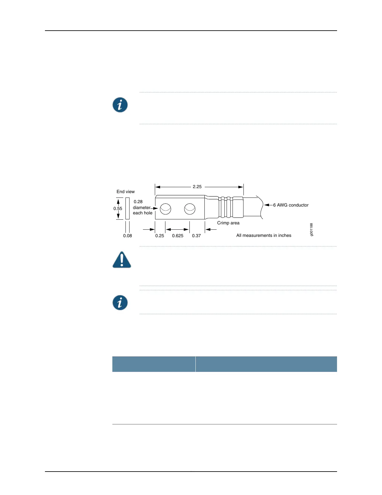
Grounding Cable Lug Specifications for an EX9200 Switch
The accessory box shipped with the switch includes one cable lug that attaches to the
grounding cable (see Figure 40 on page 98) and two UNC 1/4–20 screws used to secure
the grounding cable to the grounding points.
Figure 40: Grounding Lug for an EX9200 Switch
Crimp area
6 AWG conductor
All measurements in inches
0.28
diameter
each hole
2.25
0.25 0.370.625
g001188
0.55
End view
0.08
CAUTION: Before switch installation begins, a licensed electrician must
attach a cable lugto the grounding and power cables thatyou supply. A cable
with an incorrectly attached lug can damage the switch.
NOTE: The same cable lug is used for the DC power cables.
Grounding Cable Specifications for an EX9200 Switch
The grounding cable that you provide must meet the specificationsin Table 47 on page 98.
Table 47: Grounding Cable Specifications
Quantity and SpecificationCable Type
One 6 AWG (13.3 mm
2
), minimum 60°C wire, or one that
complies with the by the local code
For DC-powered EX9214 switches, the 48 VDC facility must
be equipped with a circuit breaker rated 40 A (–48 VDC), or
60 A (–48 VDC), and the grounding cable must be minimum
10 AWG, or one that complies with the by the local code.
Grounding
Copyright © 2017, Juniper Networks, Inc.98
EX9208 Switch Hardware Guide

 Loading...


