1. Switch off the dedicated customer site circuit breakers. Ensure that the voltage across
the DC power source cable leads is 0 V and that there is no chance that the cable
leads might become active during installation.
2. Attach the ESD grounding strap to your bare wrist, and connect the strap to the ESD
point on the chassis.
3. Move the power switch on the power supply faceplate to the off (O) position.
4. Using a screwdriver, loosen the captive screw holding the metal cover over the DIP
input mode switch. Remove the metalcover fromthe DIP input mode switch to expose
the switch.
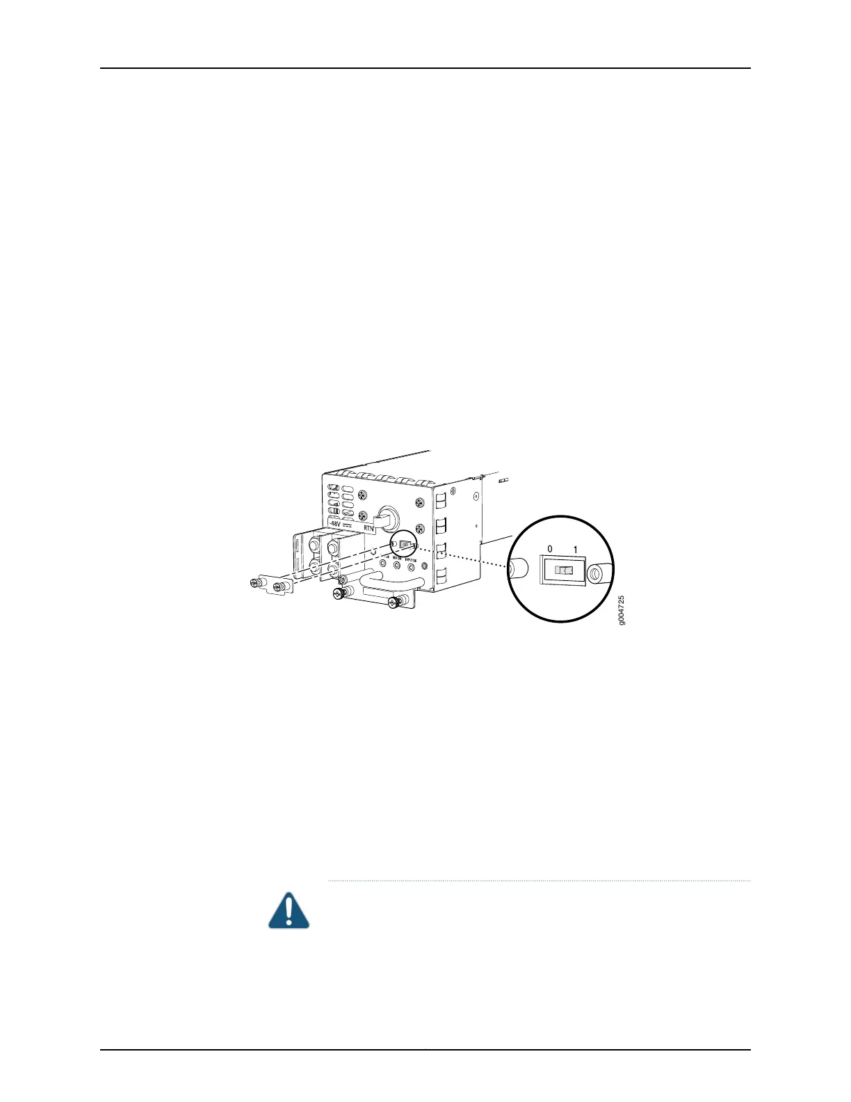
5. Check the setting of the DIP input mode switch. Use a sharp, nonconductive object
to slide the switch to the desired position. Set the input mode switch to position 0 for
60 A input and position 1 for 70 A input (see Figure 52 on page 185). This setting is used
by the power management software and needs to be set before you switch on the
power supply.
Figure 52: DIP Input Mode Switch
6. Install the metal cover over the DIP input mode switch, and use a screwdriver to tighten
the captive screw.
7. Remove the plastic cable cover from the DC power input terminals.
8. Verify that the DC power cables are correctly labeled before making connections to
the power supply. In a typical power distribution scheme where the return is connected
to chassis ground at the battery plant, you can use a multimeter to verify the resistance
of the –48V and RTN DC cables to chassis ground:
•
The cable with very large resistance (indicating an open circuit) to chassis ground
is –48V.
•
The cable with very low resistance (indicating a closed circuit) to chassis ground is
RTN.
CAUTION: You must ensure that power connections maintain the proper
polarity. The powersource cables might be labeled (+) and (–) to indicate
their polarity. There is no standard color coding for DC power cables. The
color coding used by the external DC power source at your site determines
185Copyright © 2017, Juniper Networks, Inc.
Chapter 12: Connecting the Switch to Power