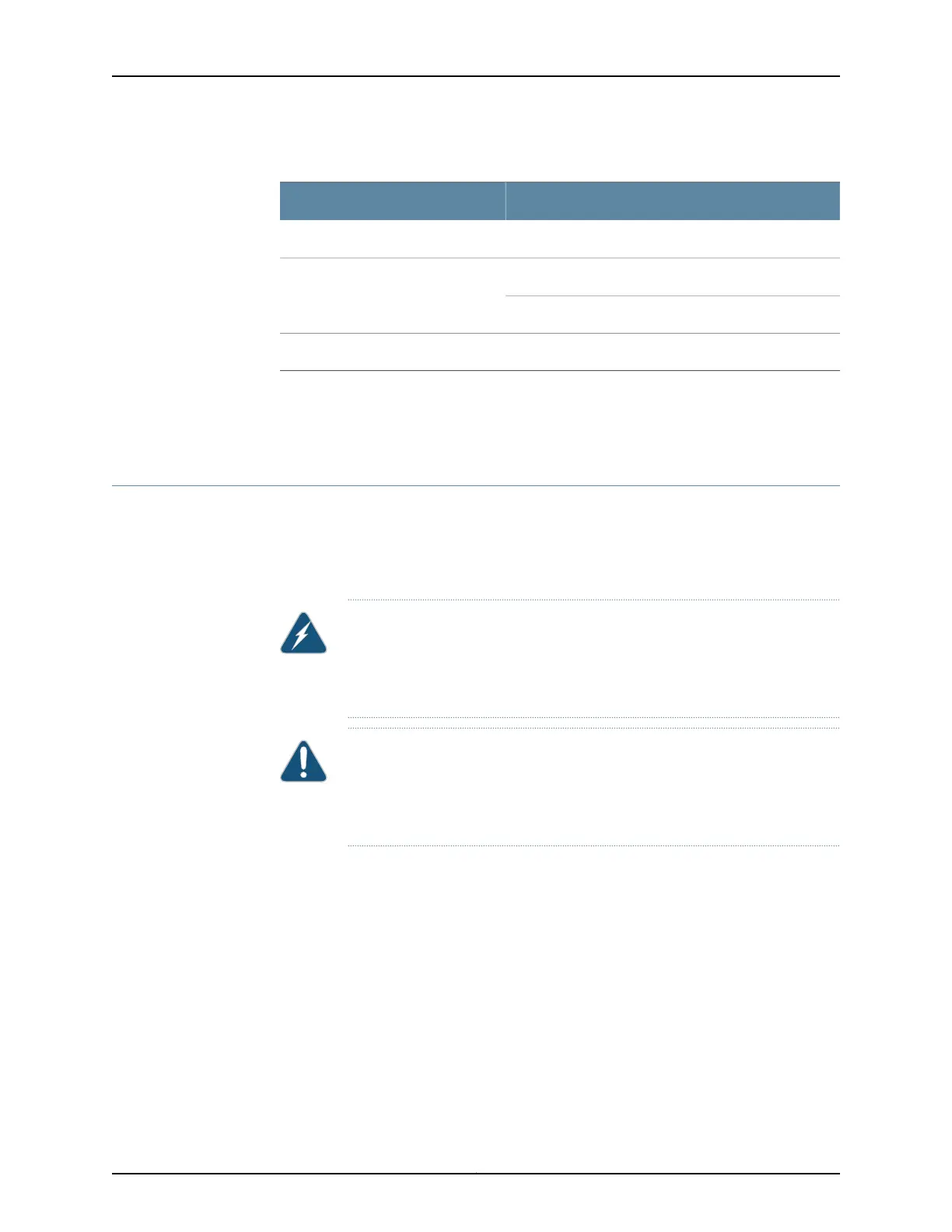
Table 46: DC Power System Specifications
Specifications
Item
2+2Redundancy
70 A (DIP=1)60 A (DIP=0)Output power (maximum) per supply
2600 W2400 W
5200 W4800 WOutput power(maximum) per system
Related
Documentation
DC Power Supply in an EX9208 Switch on page 46•
• DC Power Supply LEDs in an EX9208 Switch on page 48
Grounding Cable and Lug Specifications for EX9200 Switches
To ensure proper operation and to meet safety and electromagnetic interference (EMI)
requirements, you must connect an EX9200 switch to earth ground before you connect
power to the switch. You must use the protective earthing terminal on the switch chassis
to connect the switch to earth ground.
WARNING: The switch is installed in a restricted-access location. It has a
separateprotective earthing terminalon the chassisthat must be permanently
connected to earth ground to adequately ground the chassis and protect the
operator from electrical hazards.
CAUTION: Beforeswitchinstallationbegins, ensure thata licensed electrician
has attached an appropriate grounding lug to the grounding cable that you
supply. Using a grounding cable with an incorrectly attached lug can damage
the switch.
This topic describes:
•
Grounding Points Specifications for an EX9200 Switch on page 97
•
Grounding Cable Lug Specifications for an EX9200 Switch on page 98
•
Grounding Cable Specifications for an EX9200 Switch on page 98
Grounding Points Specifications for an EX9200 Switch
To meet safety and electromagnetic interference (EMI) requirements and to ensure
proper operation, the switch must be adequately grounded before power is connected.
To ground AC-powered and DC-powered switches, you must connect a grounding cable
to earth ground and then attach it to the chassis grounding points using the two screws
provided.
97Copyright © 2017, Juniper Networks, Inc.
Chapter 7: Planning Power Requirements