3. Taking care not to touch power supply components, pins, leads, or solder connections,
remove the power supply from its bag.
4. Flip the AC input switch next to the appliance inlet on the power supply to the off (O)
position.
5. Using both hands, place the power supply in the power supply slot on the rear of the
switch. Slide the power supply straight into the chassis until the power supply is fully
seated in the slot. Ensure the power supply faceplate is flush with any adjacent power
supply faceplates or power supply cover panels.
6. Push the handle toward the faceplate of the power supply until it is flush against the
faceplate.
7. Push the captive screw into the power supply faceplate. Ensure that the screw is
seated inside the corresponding hole on the faceplate.
8. Tighten the captive screw by turning it clockwise using the screwdriver. When the
screw is completely tight, the latch locks into the switch chassis.
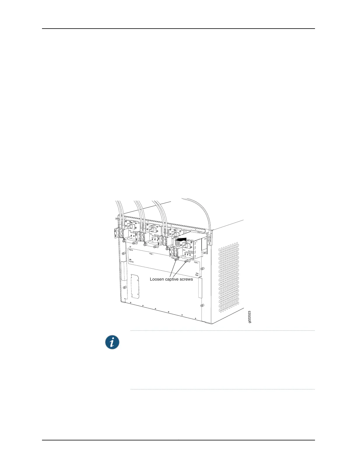
Figure 65: Installing an AC Power Supply in an EX9208 Switch
g022023
Loosen captive screws
NOTE: If you have a Juniper J-Care service contract, register any addition,
change, or upgrade of hardware components at
https://www.juniper.net/customers/support/tools/updateinstallbase/ . Failure
to do so can result in significant delays if you need replacement parts. This
note does not apply if you replace existing components with the same type
of component.
To connect power to an AC power supply, see “Connecting AC Power to an EX9208
Switch” on page 179.
Copyright © 2017, Juniper Networks, Inc.216
EX9208 Switch Hardware Guide