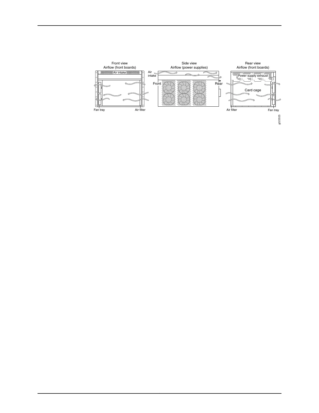
Figure 21: Airflow Through the EX9208 Switch Chassis
Fan tray
Card cage
g022025
Front view
Airflow (front boards)
Side view
Airflow (power supplies)
Front
Air filter Air filter
Air
intake
Air intake
Power supply exhaust
Fan tray
Rear
Card cage
Rear view
Airflow (front boards)
The host subsystem monitors the temperature of switch components. Under normal
operating conditions, the fans in the fan tray run at less than full speed. If a fan fails or
the ambient temperature rises above a threshold, the speed of the remaining fans is
automatically adjusted to keep the temperature within the acceptable range. If the
ambient maximum temperature specification is exceeded and the system cannot be
adequately cooled, the Routing Engine shuts down the system by disabling output power
from each power supply.
You cannot replace a single fan. If one or more fans fail, you must replace the entire fan
tray.
Related
Documentation
• Field-Replaceable Units in an EX9200 Switch on page 16
• Installing a Fan Tray in an EX9200 Switch on page 209
• Removing a Fan Tray from an EX9200 Switch on page 212
41Copyright © 2017, Juniper Networks, Inc.
Chapter 3: Cooling System and Airflow