Special Instructions to Follow Before Connecting Earth Ground to a Switch
Table 67 on page 177 lists the special instructions that you might need to follow before
connecting earth ground to a switch.
Table 67: Special Instructions to Follow Before Connecting Earth Ground to a Switch
Special InstructionsSwitch
NOTE: Some early variants of EX3200 switches for which the Juniper Networks model number on the label
next to the protective earthing terminal is from 750-021xxx through 750-030xxx require 10-24x.25 in. screws.
EX3200
NOTE: Some early variants of EX4200 switches for which the Juniper Networks model number on the label
next to the protective earthing terminal is from 750-021xxx through 750-030xxx require 10-24x.25 in. screws.
NOTE: The protective earthing terminal on an EX4200 switch mounted on four posts of a rack is accessible
through the slot on the left rear bracket only if the rack is 27.5 in. (69.85 cm) through 30.5 in. (77.47 cm)
deep for a switch mounted flush with the rack front and 29.5 in. (74.93 cm) through 32.5 in. (82.55 cm)
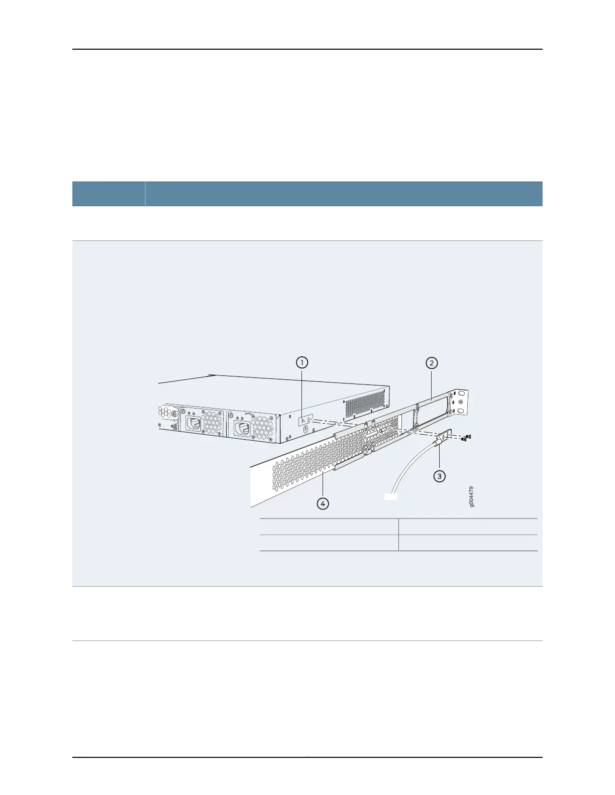
deep for a switch mounted 2 in. (5.08 cm) recessed from the rack front. See Figure 49 on page 177.
Figure 49: Connecting the Grounding Lug to a Switch Mounted on Four Posts
of a Rack
3—1— Grounding lugProtective earthing terminal
4—2— Rear mounting-bladeSide mounting-rail
NOTE: The brackets must be attached to the chassis before the grounding lug is attached. (The brackets
are shown pulled away from the chassis so that the protective earthing terminal is seen.)
EX4200
NOTE: The protective earthing terminal on an EX4300 switch mounted on four posts of a rack is accessible
through the slot on the left rear bracket only if the rack is 27.5 in. (69.85 cm) through 30.5 in. (77.47 cm)
deep for a switch mounted flush with the rack front and 29.5 in. (74.93 cm) through 32.5 in. (82.55 cm)
deep for a switch mounted 2 in. (5.08 cm) recessed from the rack front.
EX4300
177Copyright © 2017, Juniper Networks, Inc.
Chapter 12: Connecting the Switch to Power