1. Attach the ESD grounding strap to your bare wrist, and connect the strap to the ESD
point on the chassis.
2. Ensure that the power supply is fully inserted and latched securely in the chassis. See
“Installing an AC Power Supply in an EX9208 Switch” on page 215.
3. If needed, move the AC input switch next to the appliance inlet on the power supply
faceplate, to the off (O) position.
4. Insert the coupler end of the power cord into the AC appliance inlet on the AC power
supply faceplate.
5. If the AC power source outlet has a power switch, set it to the off (O) position.
6. Insert the power cord plug into an AC power source outlet.
7. If the AC power source outlet has a power switch, set it to the on (|) position.
8. Move the AC input switch next to the appliance inlet on the power supply to the on(
| ) position and observe the status LEDs on the power supply faceplate. If the power
supply is correctly installed and functioning normally, the AC OK and DC OK LEDs glow
steady green, and the PS FAIL LED is not lit.
9. Repeat steps 2 through 9 for the remaining power supplies.
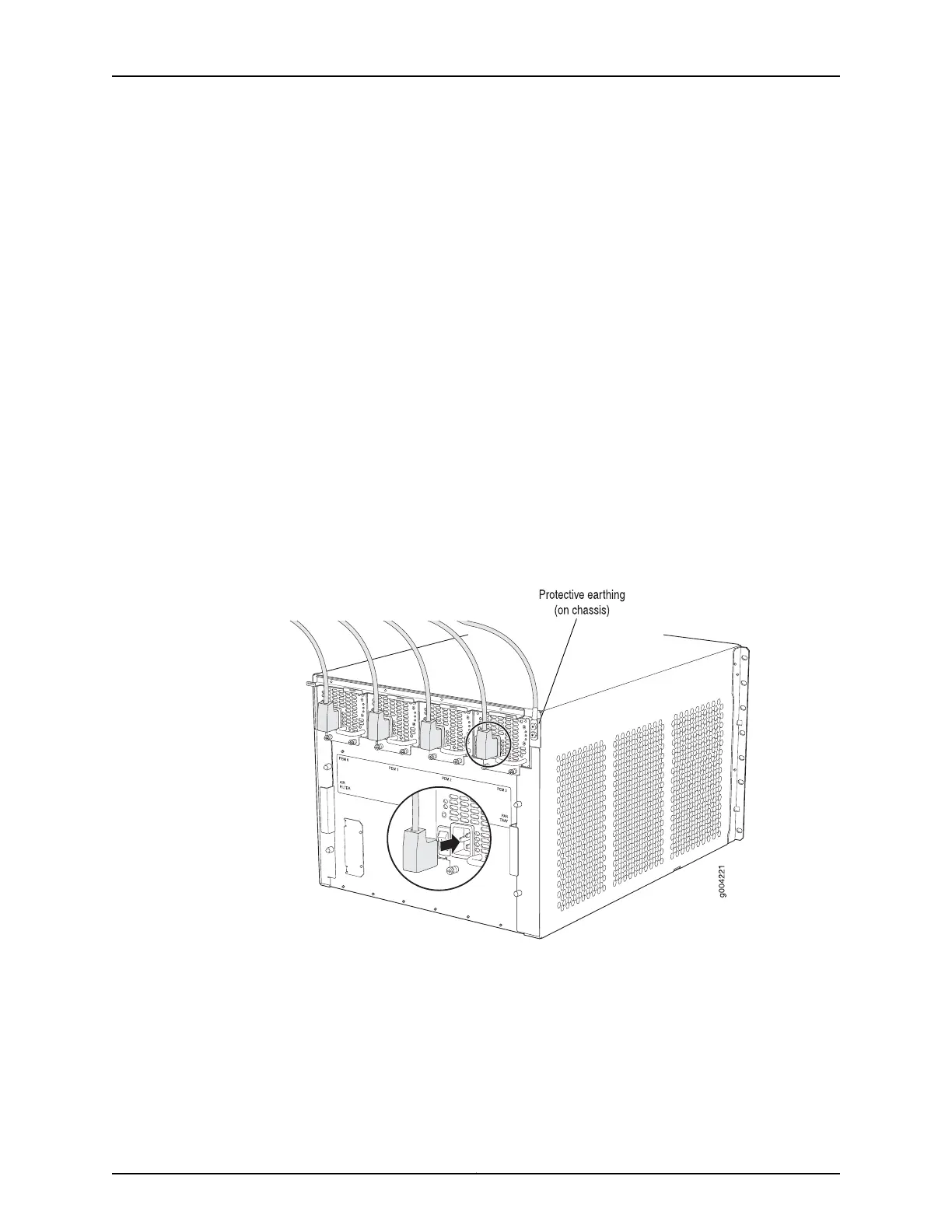
Figure 51: Connecting the Power Supply Cord to an EX9208 Switch
Related
Documentation
Powering On an AC-Powered EX9200 Switch on page 182•
• AC Power Supply in an EX9208 Switch on page 43
• AC Power Supply LEDs in an EX9208 Switch on page 45
181Copyright © 2017, Juniper Networks, Inc.
Chapter 12: Connecting the Switch to Power