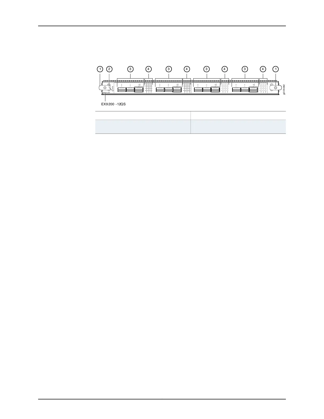
Figure 31: EX9200-12QS Line Card
g0 0 9 282
0 /3
0/ 0
0 / 4
0 /5
0 /3
0 / 4
0 /5
100G
100G
0 1 2 3
0 1 2 3
0 / 1
0 /2
0/ 0
0 / 1
0 / 2
1/ 0
1/ 1
1/2
1/ 0
1/ 1
1/2
100G
0
1
2 3
1/3
1/ 4
1/5
1/3
1/ 4
1/5
100G
0
1
2 3
1 2 3 3 3 34 4 4 4 1
EX9 200 -12QS
3—1— Gigabit Ethernet portsEjector lever
4—2— Link/Activity LEDs for the 10G/ 40G/ 100G
Ethernet ports
Line card LEDs
You can use the show version command to see the version of Junos OS for EX Series
switches loaded on the switch.
Line Card Components
The EX9200-12QS line card has:
•
Twelve rate-selectable Gigabit Ethernet ports. All ports can operate at 10-Gbps and
40-Gbps speeds. The ports are configured to operate at 10-Gbps speed by default.
The ports labeled 0/2, 0/5, 1/2, and 1/5 (see Figure 31 on page 63) can operate at
100-Gbps speed also. You can configure the port speed by using the following
command:
user@host# set chassis fpc fpc-slot pic pic-number pic-mode pic-speed number of ports
number-of-active-physical-ports
•
You can configure a port to operate at 10-Gbps speed. The ports support
QSFP+-4X10G-SR and QSFP+-4X10G-LR transceivers. If you configure the ports to
operate at 10-Gbps speed, each port operates as four 10-Gbps interfaces.
•
You can configure a port to operate at 40-Gbps speed and install a 40-gigabit QSFP+
transceiver in the port. The ports support QSFP+-40GE-SR4 and
JNP-QSFP+-40G-LR4 transceivers.
•
You can configure the ports labeled 0/2, 0/5, 1/2, and 1/5 (see Figure 31 on page 63)
to operate at 100-Gbps speed and install 100-gigabit QSFP+ transceivers in these
ports. These ports support QSFP-100GBASE-SR4 and QSFP-100GBASE-LR4
transceivers.
•
Twelve dust covers for the ports
•
Line card LED—An LED labeled OK/FAIL, which indicates the status of the line card.
See “Line Card LED in an EX9200 Switch” on page 71.
•
Network port LED—Four LEDs for each network port, the Link/Activity LED, which
indicates the link status and activity on the port. See “Network Port LEDs on Line Cards
in an EX9200 Switch” on page 33.
There are four LEDs labeled 0, 1, 2, and 3 for each port (see Figure 31 on page 63). If a
port is configured to operate at 10-Gbps speed, four 10-Gbps interfaces are created
and the LEDs labeled 0, 1, 2, and 3 for that port becomes operational. Each of these
LEDs indicates the link/activity on each four interfaces on the corresponding port. If a
63Copyright © 2017, Juniper Networks, Inc.
Chapter 5: Line Cards