Table 13: Line Card LEDs on the Craft Interface (continued)
DescriptionStatusLabel
Line card has failed.RedFAIL
Line card is not installed or functioning normally.Unlit
Alarm LEDs and Alarm Cutoff Button
Two large alarm LEDs are located at the upper right of the craft interface. The circular
LED called major alarm LED glows to indicate a critical condition that can result in a
system shutdown. The triangular LED called minor alarm LED glows to indicate a less
severe condition (warning) that requires monitoring or maintenance. Both LEDs can be
lit simultaneously.
A condition that causes an LED to be lit also activates the corresponding alarm relay
contact on the craft interface.
The alarm cutoff/lamp test (ACO/LT) button, located next to the alarm LEDs, is a control
button for alarms. You can press the ACO/LT button to deactivate major and minor
alarms. Deactivating an alarm turns off both LEDs and deactivates the device attached
to the corresponding alarm relay contact on the craft interface.
Table 14 on page 24 describes the alarm LEDs and the alarm cutoff/lamp test button.
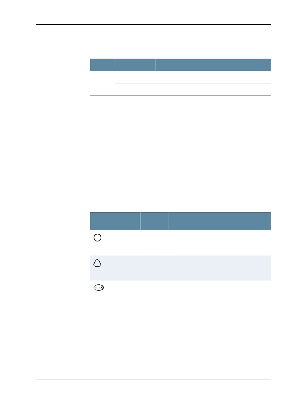
Table 14: Alarm LEDs and Alarm Cutoff/Lamp Test Button
DescriptionStatus
Alarm LEDs and
Button
Indicates a critical condition that can cause the switch
to stop functioning. Possible causes include
component removal, failure, or overheating.
Red
Major alarm LED
Indicates a serious but nonfatal error condition, such
as warning for a maintenance or a significant increase
in component temperature.
Yellow
Minor alarm LED
Deactivates major and minor alarms. Causes all LEDs
on the craft interface to light (for testing) when
pressed and held.
–
Alarm cutoff/lamp test
button
Alarm Relay Contacts
The craft interface has two alarm relay contacts for connecting the switch to external
alarm devices. Whenever a system condition triggers either the critical (major alarm) or
warning (minor alarm) alarm on the craft interface, the alarm relay contacts are also
activated. The alarm relay contacts are located on the upper right of the craft interface.
Copyright © 2017, Juniper Networks, Inc.24
EX9208 Switch Hardware Guide