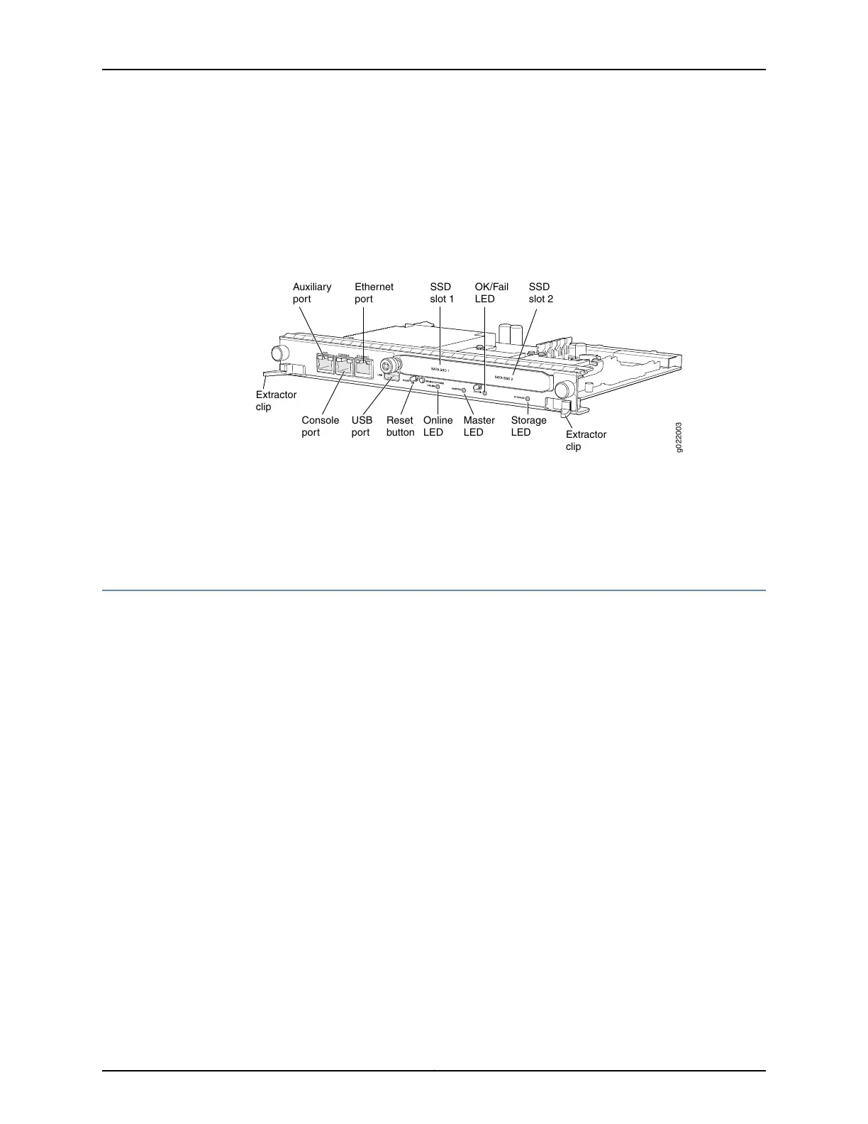
2. Plug the RJ-45 end of the serial cable into the AUX port or CONSOLE port on the RE
module. Figure 57 on page 193 shows location of AUX and CONSOLE ports on RE
module.
3. Plug the female DB-9 end into the serial port of the switch.
Figure 57: Console and Auxiliary Ports on the RE Module in EX9200
Switches
g022003
USB
port
Reset
button
Online
LED
Master
LED
OK/Fail
LED
Storage
LED
Extractor
clip
Extractor
clip
Console
port
Auxiliary
port
Ethernet
port
SSD
slot 2
SSD
slot 1
Related
Documentation
Connecting an EX9200 Switch to a Network for Out-of-Band Managementon page 191•
• Console Port and AUX Port Connector Pinout Information for an EX9200 Switch
• Cables Connecting the EX9200 Switch to Management Devices
Connecting the EX9200 Switch to an External Alarm-Reporting Device
To connect the switch to external alarm-reporting devices, attach wires to the MAJOR
ALARM and MINOR ALARM relay contacts on the craft interface. SeeFigure 58 on page 194.
A system condition that triggers the major or minor alarm LED on the craft interface also
activates the corresponding alarm relay contact.
The terminal blocks that plug into the alarm relay contacts are supplied with the switch.
They accept wire of any gauge between 28 AWG (0.08 mm
2
) and 14 AWG (2.08 mm
2
),
which is not provided. Use the gauge of wire appropriate for the external device you are
connecting.
To connect an external device to an alarm relay contact (see Figure 58 on page 194):
1. Prepare the required length of wire with gauge between 28 AWG (0.08 mm
2
) and
14 AWG (2.08 mm
2
).
2. While the terminal block is not plugged into the relay contact, use a 2.5 mm flat-blade
screwdriver to loosen the small screws on its side. With the small screws on its side
facing left, insert wires into the slots in the front of the block based on the wiring for
the external device. Tighten the screws to secure the wire.
3. Plug the terminal block into the relay contact, and use a 2.5-mm flat-blade screwdriver
to tighten the screws on the face of the block.
4. Attach the other end of the wires to the external device.
193Copyright © 2017, Juniper Networks, Inc.
Chapter 13: Connecting the Switch to the Network