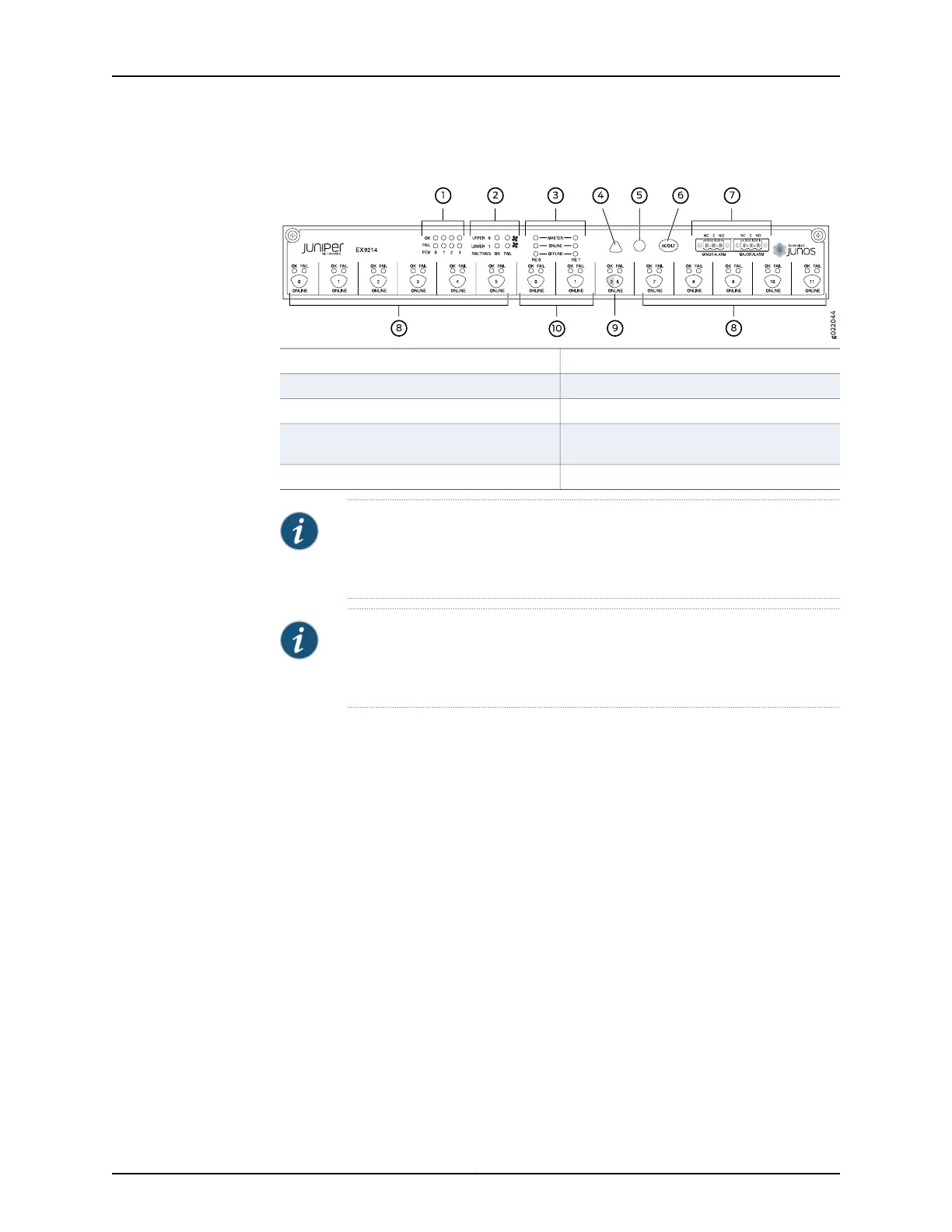
Figure 9: Craft Interface in an EX9214 Switch
6—1— Alarm cutoff/lamp test buttonPower supply LEDs
7—2— Alarm relay contactsFan LEDs
8—3— Line card LEDs and control buttonsHost subsystem LEDs
9—4— Switch Fabric/line card LED and control
button
Minor alarm LED
10—5— Switch Fabric LEDs and control buttonsMajor alarm LED
NOTE: You can install a line card or a Switch Fabric module (SF module) in
slot nine—labeled 2 | 6. The corresponding LED displays information
depending on the hardware installed in that slot.
NOTE: At leastone SwitchFabric module (SF module)with a Routing Engine
module (RE module) must be installed in the switch for the craft interface
to obtain power.
The craft interface has the following components:
•
Host Subsystem LEDs on page 21
•
Fan LEDs on page 22
•
Power Supply (PEM) LEDs on page 22
•
Switch Fabric LEDs and Control Buttons on page 23
•
Line Card LEDs and Control Buttons on page 23
•
Alarm LEDs and Alarm Cutoff Button on page 24
•
Alarm Relay Contacts on page 24
Host Subsystem LEDs
Each host subsystem (RE module with SF module) has three LEDs, located on the upper
left of the craft interface, to indicate its status. The LEDs grouped with labels RE0 and
RE1 show the status of the host subsystems installed in the switch. Table 9 on page 22
describes the functions of these LEDs.
21Copyright © 2017, Juniper Networks, Inc.
Chapter 2: Chassis Components and Descriptions