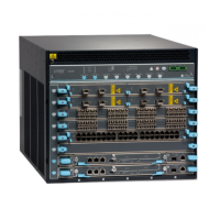
NOTE: In EX9204 and EX9208 switches,we recommend thatyou install two
host subsystems for redundant protection. If you install only one host
subsystem, we recommend that you install it in slot 0. In EX9214 switches,
we recommend that you install three host subsystems for redundant
protection. If you install only two host subsystems, we recommend that you
install it in slot 0 and 1.
Each host subsystem has LEDs in the craft interface that display its status. See “Craft
Interface in an EX9200 Switch” on page 19.
Related
Documentation
Taking the Host Subsystem Offline in an EX9200 Switch on page 226•
• Maintaining Host Subsystem in EX9200 Switches on page 275
• Understanding EX9204 Switch Component and Functionality Redundancy
• Understanding EX9208 Switch Component and Functionality Redundancy on page 18
• Understanding EX9214 Switch Component and Functionality Redundancy
• Routing Engine Module in an EX9200 Switch on page 27
• Switch Fabric Module in an EX9200 Switch on page 29
Network Port LEDs on Line Cards in an EX9200 Switch
Each SFP, SFP+, QSFP+, CFP, and RJ-45 port on the faceplate of line cards has an LED,
the Link/Activity LED, which indicates the link status and activity on the port. Each RJ-45
port has an additional LED, the Status LED, which indicates the status of the port
parameters.
Table 15 on page 33 describes the Link/Activity LED.
Table 15: Network Port LEDs on Line Cards in an EX9200
Switch—Link/Activity LED
State and DescriptionColorLED
•
On steadily—The port and the link are active,
but there is no link activity.
•
Blinking—The port and the link are active,and
there is link activity.
•
Off—The port is not active.
GreenLink/Activity
The Status LED in 10/100/1000BASE-T RJ-45 Ethernet network port indicates the status
of one of the three port parameters—administrative status, speed, and duplex mode
status.
Table 16 on page 34 describes the Status LED.
33Copyright © 2017, Juniper Networks, Inc.
Chapter 2: Chassis Components and Descriptions

 Loading...