Appendix A: Installation and Setup
Linx 4900 Operating Manual 158 MP65492–1
A.4 Setting up Product Sensors
The Linx 4900 printer uses product sensors to detect the presence of the
product to be printed on. There are variations in the way the printer
interprets a trigger signal. However, it usually prints a message in response
to such a signal from the product sensor.
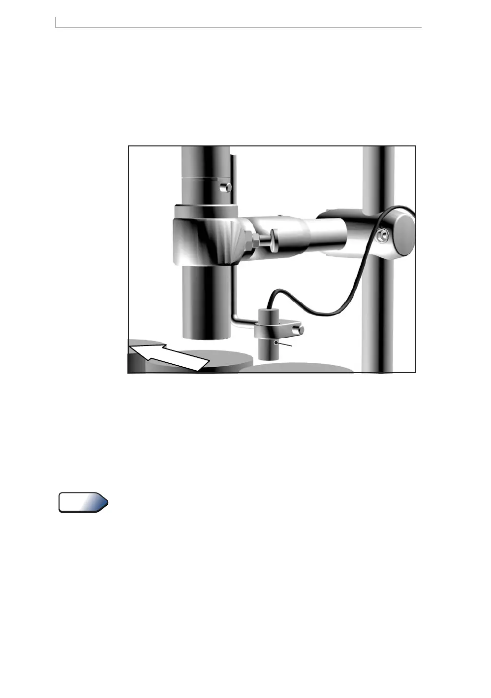
Figure A-3 Setting up the Product Sensor
Typically, the product sensor is mounted upstream of the printhead, and the
distance between printhead and product sensor would be less than one
message spacing.
A delay between the triggering product sensor and the start of printing is
set through the Print Delay option in the user interface. This allows direct
setting of the print position.
For information about setting the print delay, see ‘To Set the Print Delay’
on page 98.
The following product sensor types are available from Linx:
• Fibre optic control unit, 5 m D-type
• Retro-reflective light beam, 5 m D-type
• Inductive switch, 5 m D-type
• Reflection light beam scanner, 5 m D-type
• Background suppression sensor, 5 m D-type
• Colour registration mark scanner, 5 m D-type
Direction of conveyor
Product sensor
mounted on bracket
and positioned before
the printhead.
68553
See Also
4900 Op Manual.book Page 158 Tuesday, September 9, 2003 12:32 PM