215575 250 Revision B
$
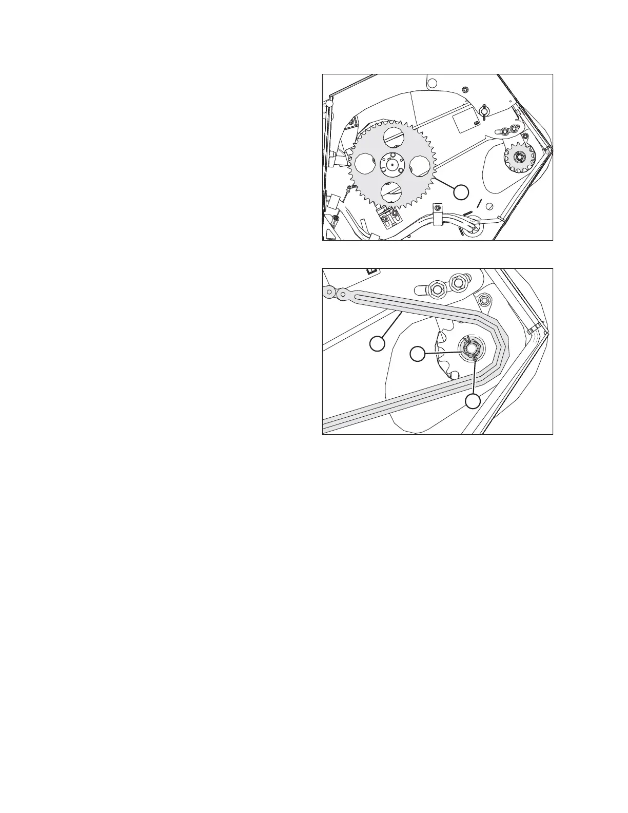
Figure 5.69: Driven Sprocket
4. If the header is not attached to the combine, place a pry
bar or equivalent through a hole in the driven sprocket (A)
and against the frame to stop the driveshaft from rotating.
$
%
&
Figure 5.70: Drive Sprocket
5. Torque castle nut (A) to 68 Nm (50 lbf∙ft). If the slot in the
castle nut and the hole in the driveshaft are not aligned,
continue to tighten the castle nut to 81 Nm (60 lbf∙ ft). If the
castle nut’s hole and the hole in the driveshaft are still not
aligned, back off the castle nut until it is possible to install
cotter pin (B).
6. Install cotter pin (B) into the driveshaft hole. Bend the ends
of the cotter pin around castle nut (A).
7. Set the tension of drive chain (C) . For instructions, refer to
Adjusting Auger Drive Chain Tension, page 244.
8. Close the left endshield. For instructions, refer to 3.3.2
Closing Left Endshield, page 26.
MAINTENANCE AND SERVICING