215575 277 Revision B
Figure 5.132: Left Side Shown – Right Side Opposite
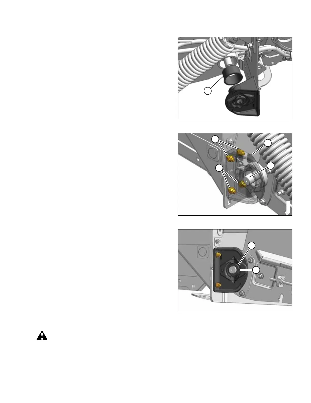
20. Replace bushing (A) if necessary.
Figure 5.133: Right Rear Deck
21. Place bearing support (B) on roller shaft (A).
22. Position the bearing support’s base against the frame and
align the mounting holes.
23. Install two M12 x 30 carriage bolts (C) in the upper holes
and two M12 x 40 carriage bolts (D) in the lower holes.
Secure the bolts with lock nuts.
NOTE:
Ensure that the height controller is not damaged when
installing the bolts.
Figure 5.134: Right Rear Deck
24. Install lock collar (A) onto the bearing. Lock the collar in the
direction of shaft rotation with a punch and hammer, then
tighten set screw (B).
CAUTION
Never start or move the machine until you are sure all bystanders have cleared the area.
25. Start the combine, and raise the header fully. Shut down the combine, and remove the key from the ignition.
26. Remove the wooden block.
MAINTENANCE AND SERVICING