215575 52 Revision B
$
&
%
'
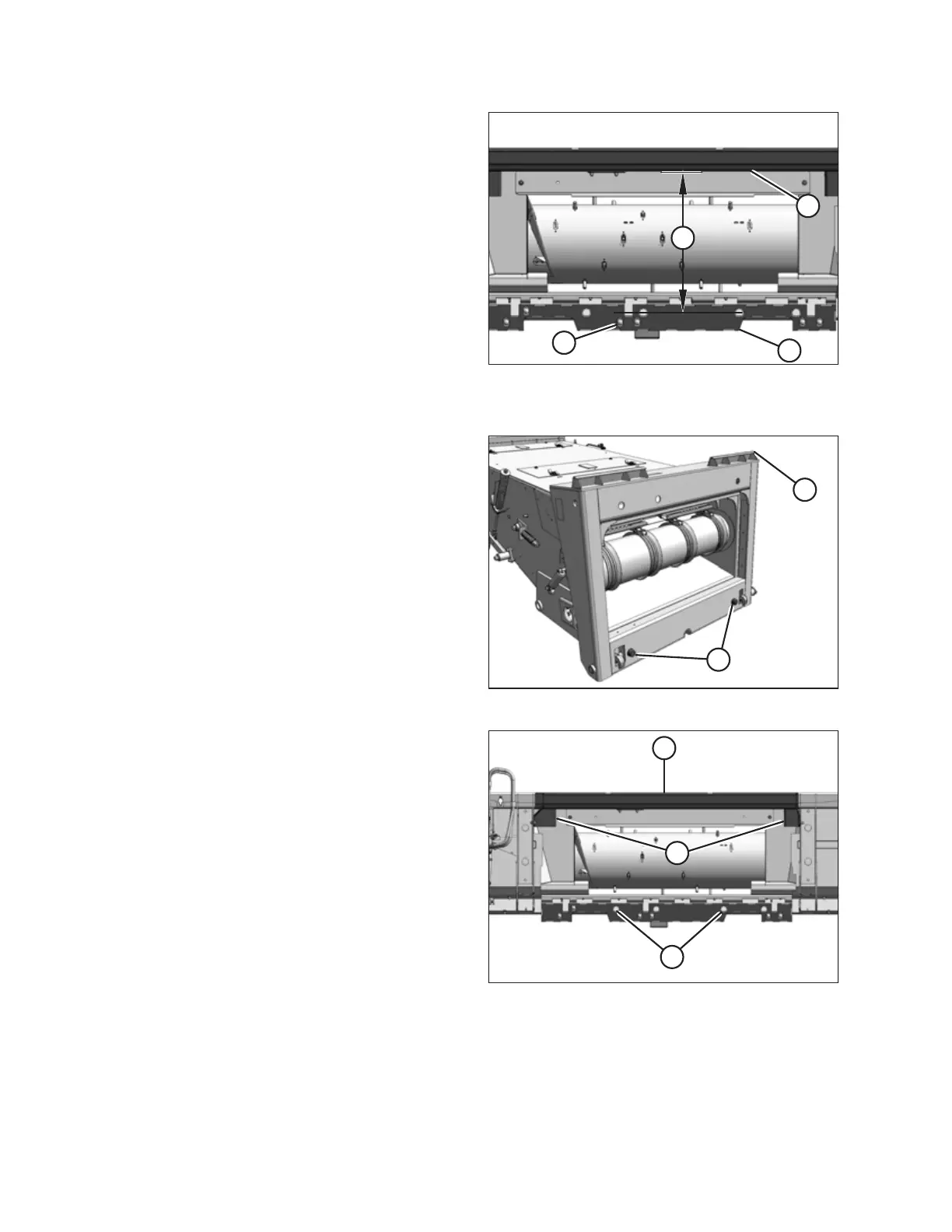
Figure 3.53: Lower Beam Adjustment
2. Check distance (A) between the underside of top beam (B)
and the alignment holes in lower beam (C) on the header.
Distance (A) should measure 793–799 mm (31–31 1/2 in.).
3. If necessary, loosen six bolts (D) and adjust lower beam (C)
to adjust distance (A) to the correct value. Tighten
the bolts.
4. Start the engine.
$
&
Figure 3.54: AGCO Combine Feeder House
5. Drive the combine slowly up to the header until the top of
feeder house (A) is directly under top beam (B), and
alignment pins (C) on feeder house are aligned with
holes (D) in the header frame.
NOTE:
Take notice of two guides (E) on either side of the header
opening.
%
(
'
Figure 3.55: Header Opening – All AGCO Combines
except Gleaner
®®
R and S Series
OPERATION