Allocation of the 9-pin D-sub female connector "OUT"③③
Pin allocation acc. to
DIN 41642
Signal Color acc. to
DIN 47100
Description
Cable sheath pea green Special InterBus cable (certified)
Housing S Screen
1 ---------------------- DO1 yellow not inverted, data output
2 ---------------------- DI1 gray not inverted, data input
3 ---------------------- GND brown signal ground
4 not connected
5 not connected
6 ---------------------- IDO1 green inverted, data output
7 ---------------------- IDI1 pink inverted, data input
8 not connected
9 not connected
* only if necessary
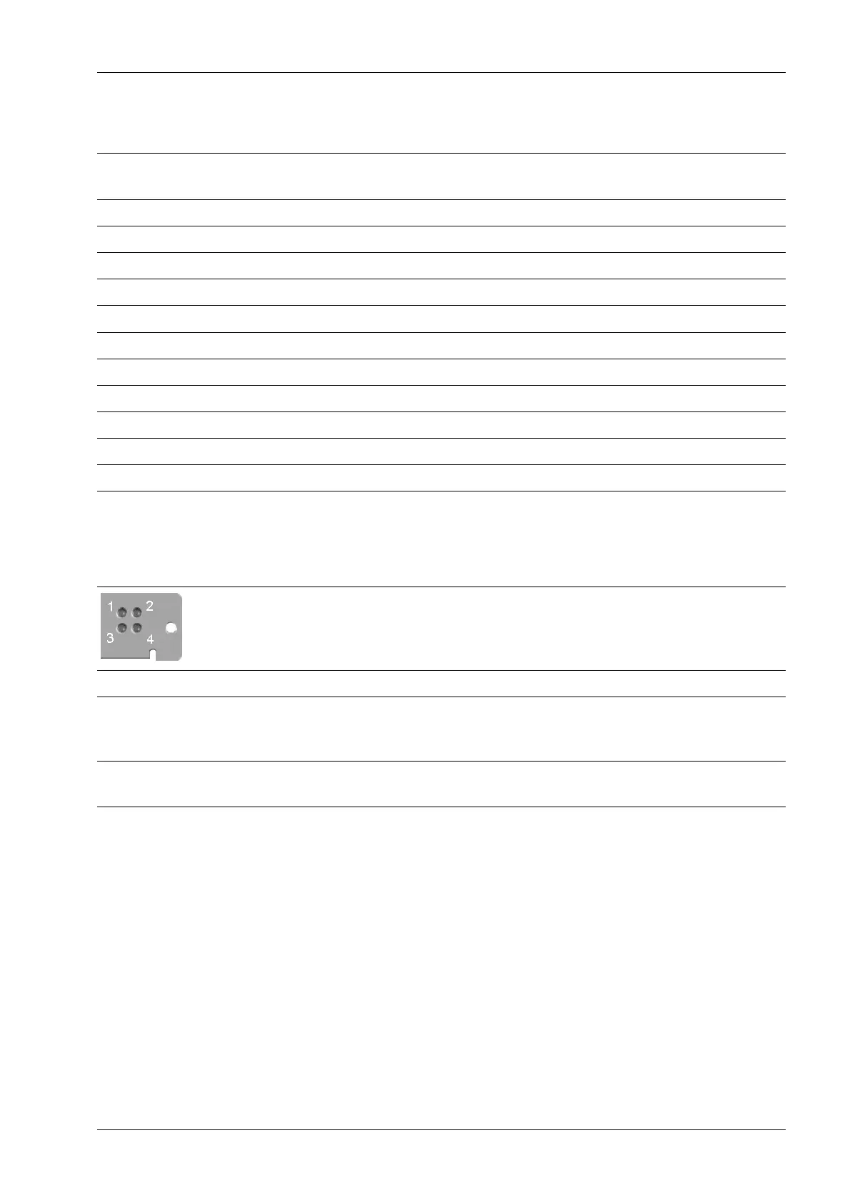
4.6.14.1 LEDs in the module cover
The module cover can be found at the rear of the device.
⑥⑥
LED 1
CC/RC
LED 2
BA
LED 3
RD
LED 4
TR
Off
Constant green Cable OK, no reset
mode in the master
Bus is active PCP communication
is active, hold = 500
ms
Constant red Remote bus is not
active
4 Device installation X3 Process Indicator PR 5410
Minebea Intec EN-103