— A-6 —
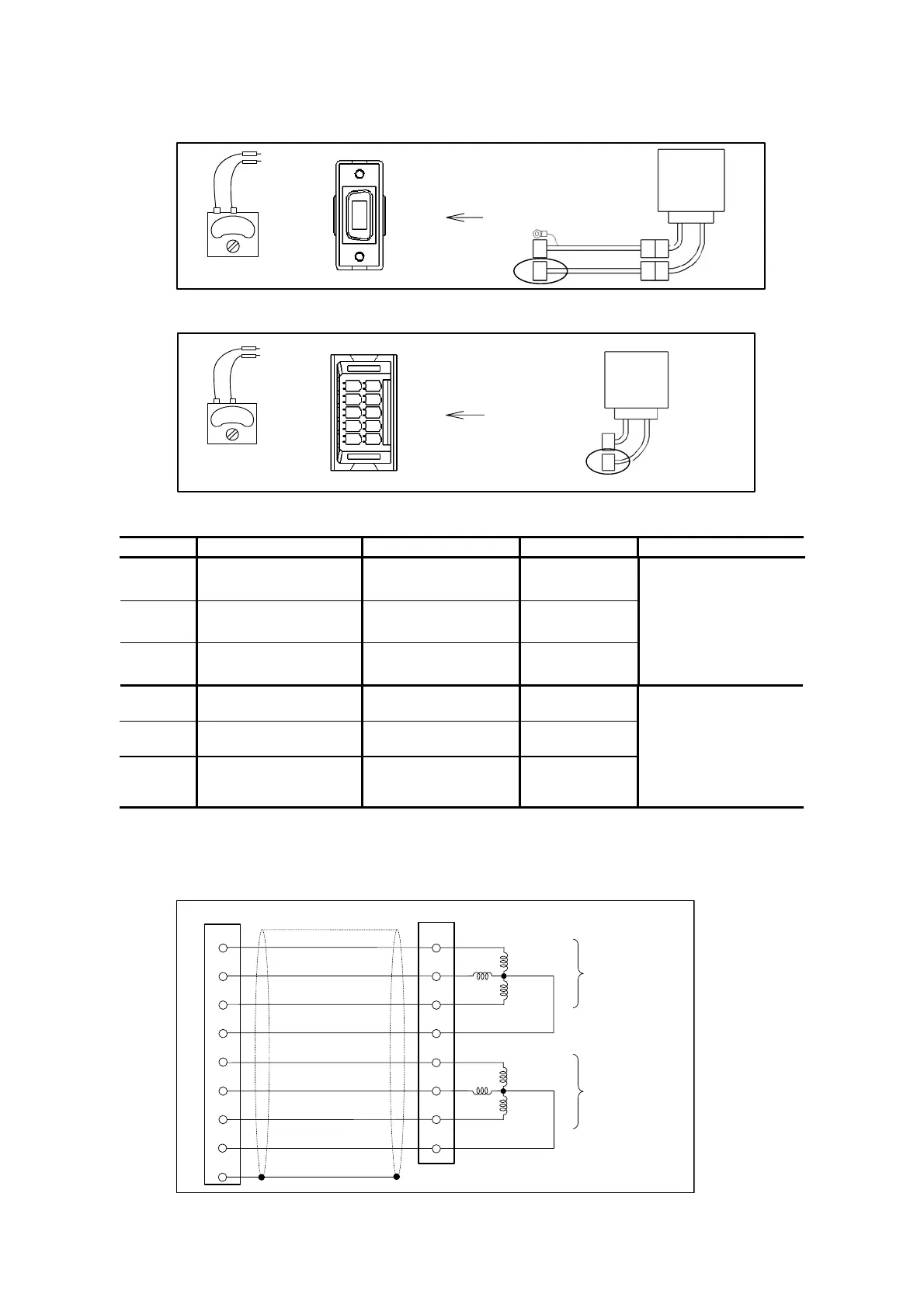
1. Resistance check of the resolver cable
Fig A-7: Check with the Cable set
Tester
Ω/
(1)
(2)
(3)
(4)
(5)
(6)
(7)
(8)
(9)
(10)
(11)
(12)
(13)
(14)
Fig A-8: Check the Motor only
Tester
Ω/
(6)
(7)
(8)
(9)
(10)
(1)
(2)
(3)
(4)
(5)
Table A-7: Checking points of a resolver with absolute position sensor and winding resistance
Cable connector Motor connector Result Specification
INC-A
(1) ↔ (9)
(INC-A) (INC・COM)
(1) ↔ (4)
(INC-A) (INC・COM)
INC-B
(2) ↔ (9)
(INC-B) (INC・COM)
(2) ↔ (4)
(INC-B) (INC・COM)
INC-C
(3) ↔ (9)
(INC-C) (INC・COM)
(3) ↔ (4)
(INC-C) (INC・COM)
1.Resistance
• PS 1type: 8.3 Ω±1
• PS 3 type: :9.8 Ω±1
2. Variation between
each phase A, B and
C shall be 1.0 Ω or
less.
ABS-A
(6) ↔ (8)
(ABS-A) (ABS・COM)
(6) ↔ (9)
(ABS-A) (ABS・COM)
ABS-B
(6) ↔ (8)
(ABS-B) (ABS・COM)
(7) ↔ (9)
(ABS-B) (ABS・COM)
ABS-C
(7) ↔ (8)
(ABS-C) (ABS・COM)
(8) ↔ (9)
(ABS-C) (ABS・COM)
1.Resistance
• PS1 type: 8.3 Ω±1
• PS3 type: 9.8 Ω±1
2. Variation between
each phase A, B and
C shall be 1.0 Ω or
less.
Please ask NSK sales or representative for the specifications of the Motor with special winding,
and the Cable longer than 4 m.
Fig A-9: Connection of the Motor with the absolute position sensor [Reference only]
Connector of Driver Unit Connector of Motor
INC-A
INC-B
INC-C
INC-common
ABS-A
ABS-B
ABS-C
ABS-common
FG (shielded wire)
Common
øC
øB
ø A
Incremental
resolver
Absolute resolver
øA
øB
øC
Common
(1)
(2)
(3)
(5)
(6)
(7)
(8)
(9)
(14)
(1)
(2)
(3)
(6)
(7)
(8)
(9)
(4)

 Loading...


