5V Analog Comparator (ACMPV1)
MC9S12G Family Reference Manual Rev.1.27
250 NXP Semiconductors
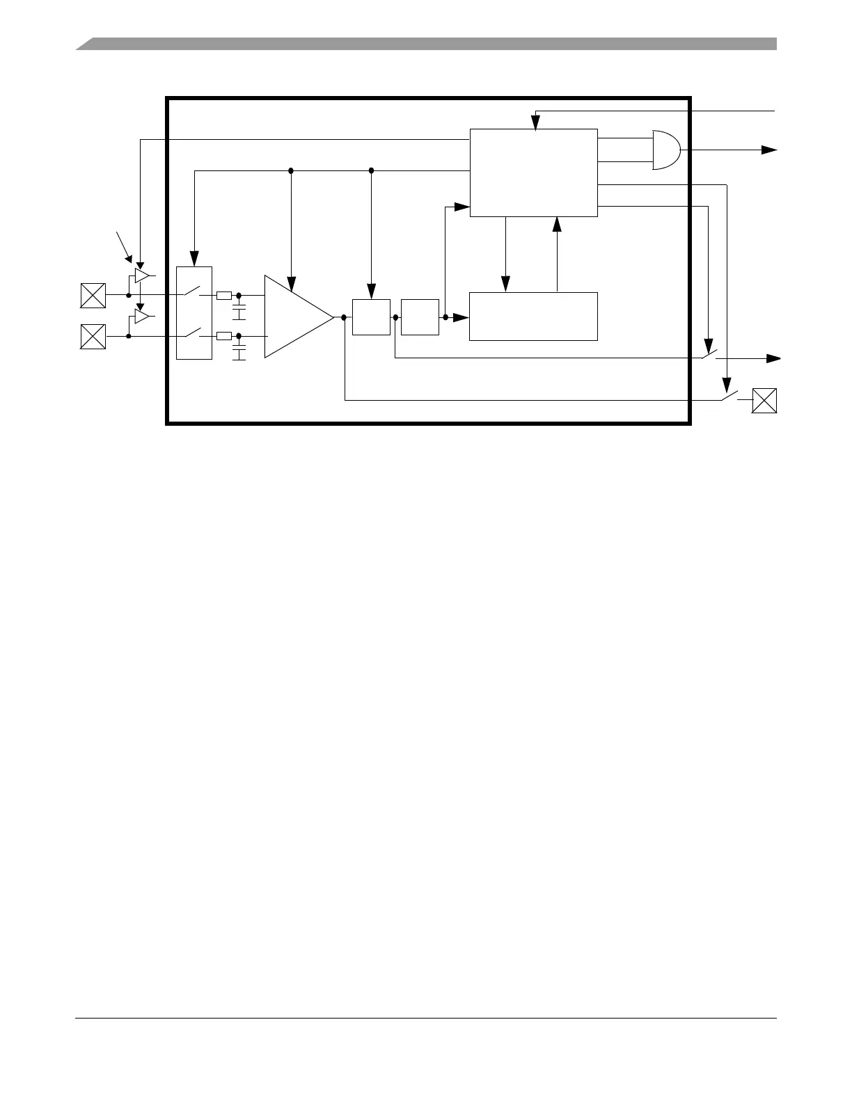
Figure 3-1. ACMP Block Diagram
Figure 3-2.
3.4 External Signals
The ACMP has two analog input signals, ACMPP and ACMPM, and one digital output, ACMPO. The
associated pins are defined by the package option.
The ACMPP signal is connected to the non-inverting input of the comparator. The ACMPM signal is
connected to the inverting input of the comparator. Each of these signals can accept an input voltage that
varies across the full 5V operating voltage range. The module monitors the voltage on these inputs
independent of any other functions in use (GPIO, ADC).
The raw comparator output signal can optionally be driven on an external pin.
3.5 Modes of Operation
1. Normal Mode
The ACMP is operating when enabled and not in STOP mode.
2. Shutdown Mode
The ACMP is held in shutdown mode either when disabled or during STOP mode. In this case the
supply of the analog block is disconnected for power saving. ACMPO drives zero in shutdown
mode.
Interrupt
Control
ACMP IRQ
Control & Status
Register
ACMOD
SET ACIF
ACE
ACIF
ACIE
ACOPE
ACMPO
ACO
ACMPP
ACMPM
To Input
+
_
(enable)
ACICE
Capture
SyncHold
Channel
ACDIEN
digital
buffer
input
INTERNAL BUS

 Loading...


