Port Integration Module (S12GPIMV1)
MC9S12G Family Reference Manual Rev.1.27
NXP Semiconductors 171
2.3.11 Pins PJ7-0
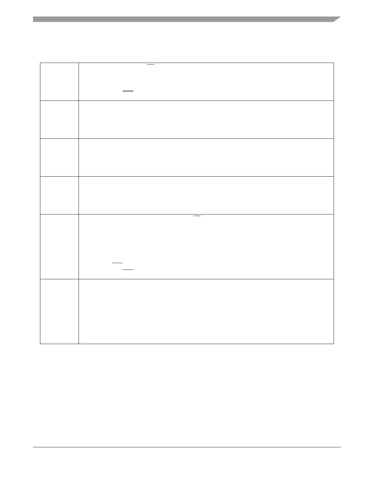
Table 2-15. Port J Pins PJ7-0
PJ7 • 64/100 LQFP: The SPI2 SS signal is mapped to this pin when used with the SPI function. Depending
on the configuration of the enabled SPI2 the I/O state is forced to be input or output.
• 64/100 LQFP: Pin interrupts can be generated if enabled in input or output mode.
• Signal priority:
64/100 LQFP: SS2
> GPO
PJ6 • 64/100 LQFP: The SPI2 SCK signal is mapped to this pin when used with the SPI function. Depending
on the configuration of the enabled SPI2 the I/O state is forced to be input or output.
• 64/100 LQFP: Pin interrupts can be generated if enabled in input or output mode.
• Signal priority:
64/100 LQFP: SCK2 > GPO
PJ5 • 64/100 LQFP: The SPI2 MOSI signal is mapped to this pin when used with the SPI function. Depending
on the configuration of the enabled SPI2 the I/O state is forced to be input or output.
• 64/100 LQFP: Pin interrupts can be generated if enabled in input or output mode.
• Signal priority:
64/100 LQFP: MOSI2 > GPO
PJ4 • 64/100 LQFP: The SPI2 MISO signal is mapped to this pin when used with the SPI function.Depending
on the configuration of the enabled SPI2 the I/O state is forced to be input or output.
• 64/100 LQFP: Pin interrupts can be generated if enabled in input or output mode.
• Signal priority:
64/100 LQFP: MISO2 > GPO
PJ3 • Except 20 TSSOP and 32 LQFP: The SPI1 SS
signal is mapped to this pin when used with the SPI
function. Depending on the configuration of the enabled SPI1 the I/O state is forced to be input or
output.
• 48 LQFP: The PWM channel 7 signal is mapped to this pin when used with the PWM function. The
enabled PWM channel forces the I/O state to be an output.
• Except 20 TSSOP and 32 LQFP: Pin interrupts can be generated if enabled in input or output mode.
• Signal priority:
48 LQFP: SS1
> PWM7 > GPO
64/100 LQFP: SS1 > GPO
PJ2 • Except 20 TSSOP and 32 LQFP: The SPI1 SCK signal is mapped to this pin when used with the SPI
function. Depending on the configuration of the enabled SPI1 the I/O state is forced to be input or
output.
• 48 LQFP: The TIM channel 7 signal is mapped to this pin when used with the TIM function. The TIM
forces the I/O state to be an output for a timer port associated with an enabled output.
• Except 20 TSSOP and 32 LQFP: Pin interrupts can be generated if enabled in input or output mode.
• Signal priority:
48 LQFP: SCK1 > IOC7 > GPO
64/100 LQFP: SCK1 > GPO

 Loading...


