S12 Clock, Reset and Power Management Unit (S12CPMU)
MC9S12G Family Reference Manual Rev.1.27
NXP Semiconductors 391
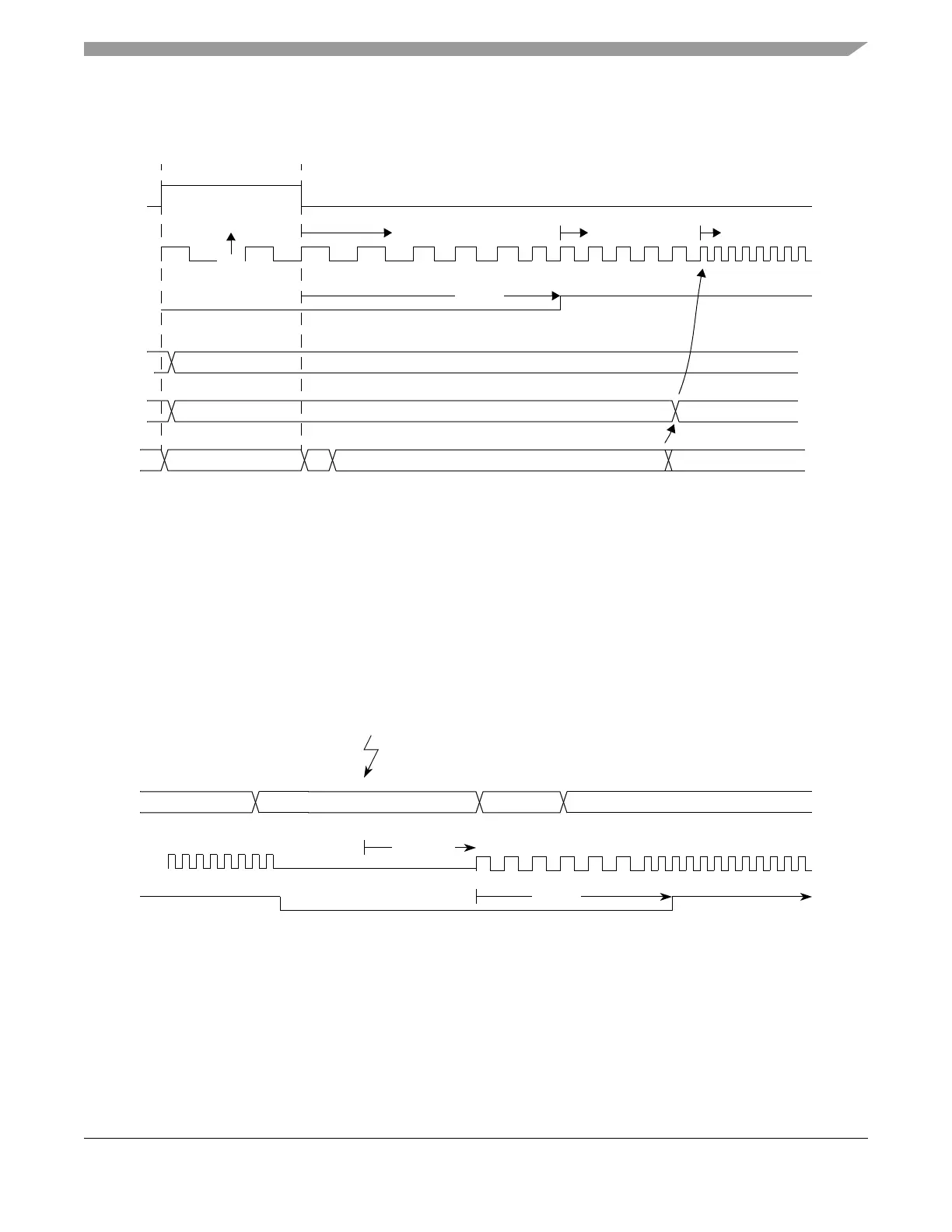
Figure 10-30. Startup of clock system after Reset
10.4.3 Stop Mode using PLLCLK as Bus Clock
An example of what happens going into Stop Mode and exiting Stop Mode after an interrupt is shown in
Figure 10-31. Disable PLL Lock interrupt (LOCKIE=0) before going into Stop Mode.
Figure 10-31. Stop Mode using PLLCLK as Bus Clock
10.4.4 Full Stop Mode using Oscillator Clock as Bus Clock
An example of what happens going into Full Stop Mode and exiting Full Stop Mode after an interrupt is
shown in Figure 10-32.
System
PLLCLK
Reset
f
VCORST
CPU
reset state
vector fetch, program execution
LOCK
POSTDIV
$03 (default target f
PLL
=f
VCO
/4 = 12.5MHz)
f
PLL
increasing
f
PLL
=16MHz
t
lock
SYNDIV
$18 (default target f
VCO
=50MHz)
$01
f
PLL
=32 MHz
example change
of POSTDIV
768 cycles
) (
PLLCLK
CPU
LOCK
t
lock
STOP instructionexecution
interrupt continue execution
wakeup
t
STP_REC

 Loading...


