S12S Debug Module (S12SDBGV2)
MC9S12G Family Reference Manual Rev.1.27
NXP Semiconductors 307
• 4-stage state sequencer for trace buffer control
— Tracing session trigger linked to Final State of state sequencer
— Begin and End alignment of tracing to trigger
8.1.4 Modes of Operation
The DBG module can be used in all MCU functional modes.
During BDM hardware accesses and whilst the BDM module is active, CPU monitoring is disabled. When
the CPU enters active BDM Mode through a BACKGROUND command, the DBG module, if already
armed, remains armed.
The DBG module tracing is disabled if the MCU is secure, however, breakpoints can still be generated.
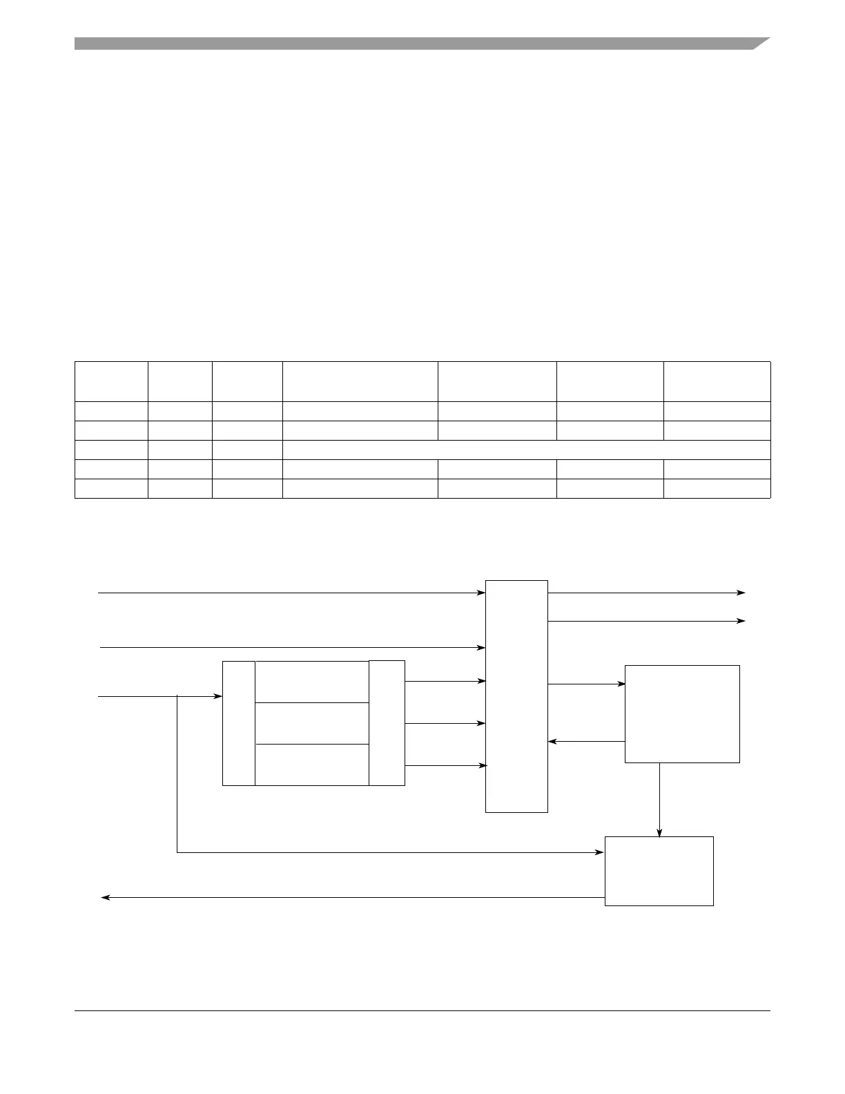
8.1.5 Block Diagram
Figure 8-1. Debug Module Block Diagram
Table 8-2. Mode Dependent Restriction Summary
BDM
Enable
BDM
Active
MCU
Secure
Comparator
Matches Enabled
Breakpoints
Possible
Tagging
Possible
Tracing
Possible
xx1 Yes Yes Yes No
0 0 0 Yes Only SWI Yes Yes
0 1 0 Active BDM not possible when not enabled
1 0 0 Yes Yes Yes Yes
110 No No No No
CPU BUS
TRACE BUFFER
BUS INTERFACE
TRANSITION
MATCH0
STATE
COMPARATOR B
COMPARATOR C
COMPARATOR A
STATE SEQUENCER
MATCH1
MATCH2
TRACE
READ TRACE DATA (DBG READ DATA BUS)
CONTROL
SECURE
BREAKPOINT REQUESTS
COMPARATOR
MATCH CONTROL
TRIGGER
TAG &
MATCH
CONTROL
LOGIC
TAGS
TAGHITS
STATE
TO CPU

 Loading...


